
Adjustable clamping device for mounting slitting blade and using method of adjustable clamping device

A clamping device and a technology for installation, which is applied in the direction of workpiece clamping devices, metal processing, metal processing equipment, etc., can solve the problems of large manpower and material resources, increase the cost of blade installation, etc., and achieve the effect of stably supporting the support block

Inactive Publication Date: 2022-03-29
南京金特利精密机械有限公司
View PDF0 Cites 0 Cited by
  • Summary
  • Abstract
  • Description
  • Claims
  • Application Information

AI Technical Summary

Problems solved by technology

[0003] The purpose of the present invention is to provide an adjustable clamping device for slitting blade installation and its use method, which has the advantage of automation and solves the problem of manual installation of most slitting blades at present, which requires a lot of investment. Manpower and material resources greatly increase the cost of blade installation

Method used


Image

  • Adjustable clamping device for mounting slitting blade and using method of adjustable clamping device
  • Adjustable clamping device for mounting slitting blade and using method of adjustable clamping device
  • Adjustable clamping device for mounting slitting blade and using method of adjustable clamping device

Examples


Embodiment Construction

[0027] The following will clearly and completely describe the technical solutions in the embodiments of the present invention with reference to the accompanying drawings in the embodiments of the present invention. Obviously, the described embodiments are only some, not all, embodiments of the present invention. Based on the embodiments of the present invention, all other embodiments obtained by persons of ordinary skill in the art without making creative efforts belong to the protection scope of the present invention.

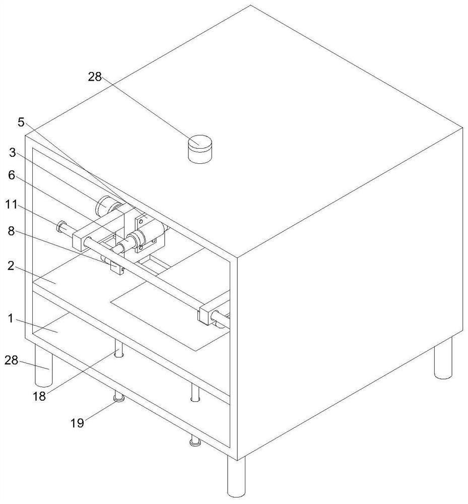
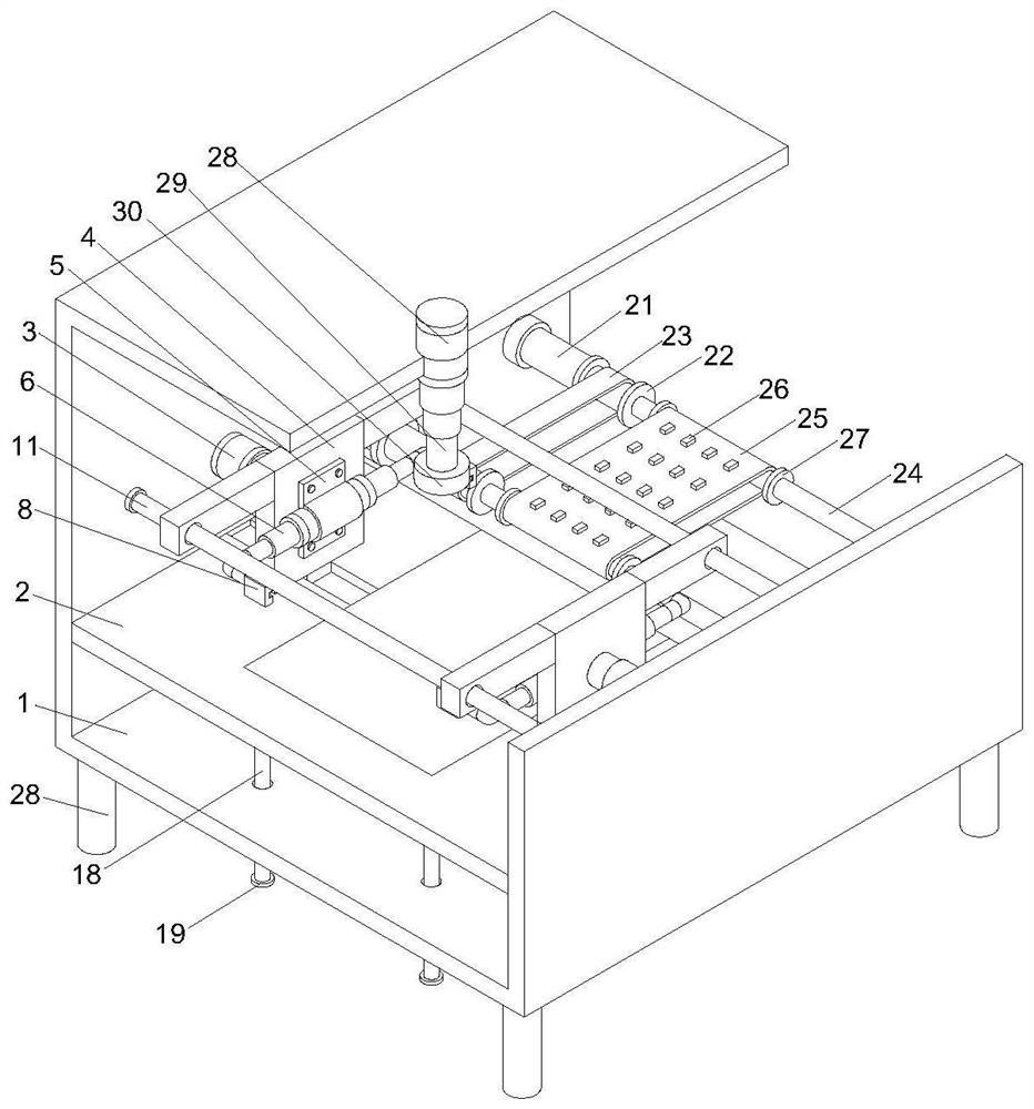
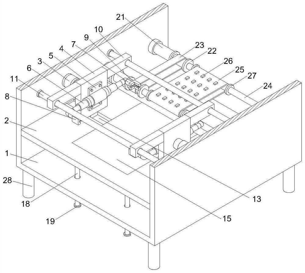
[0028] The installation box 1 of the present invention, the limit plate 2, the first electric rod 3, the first movable plate 4, the installation block 5, the second electric rod 6, the first fixed column 7, the clamping block 8, the first limit Slot 9, support block 10, first limit rod 11, first limit block 12, second limit groove 13, third electric rod 14, second movable plate 15, placement groove 16, third limit groove 17 , the second limit rod 18, the secon...


PUM


Abstract

The adjustable clamping device comprises a mounting box body, the lower end of an inner cavity of the mounting box body is fixedly connected with a limiting plate, the upper ends of the two sides of the inner cavity of the mounting box body are fixedly connected with first electric rods, and the output ends of the first electric rods are fixedly connected with first movable plates; and one side of the first movable plate is movably connected with a mounting block through a bolt, and an inner cavity of the mounting block is movably connected with a second electric rod. By arranging the mounting box body, the effect of stably supporting a limiting plate and a first electric rod is achieved, by arranging the first electric rod, the effect of driving a first movable plate to perform transverse displacement is achieved, by arranging the first movable plate, the effect of stably supporting a mounting block is achieved, and the problem that when most of slitting blades are mounted at present, the cutting efficiency is greatly improved is solved. And manual installation is adopted, so that a large amount of manpower and material resources need to be invested, and the installation cost of the blade is greatly improved.

Description

technical field [0001] The invention relates to the technical field of blades, in particular to an adjustable clamping device for installing a slitting blade and a usage method thereof. Background technique [0002] The blade used for mechanical processing in the die-cutting industry is the slitting blade, which is widely used because of its simple structure, and there are many types, mainly including metallurgical knives, slitting and slitting blades, rubber mechanical blades, leather mechanical knives, Papermaking machinery knives, pipe cutting machinery knives, slitting machinery knives, carton machinery knives, dotted line blades, flower-shaped blades, round blades, strips, and some special-shaped blades. At present, most of the cutting blades are installed. Operators are required to manually fix the installation, so a lot of manpower and material resources are required, which greatly increases the cost of blade installation. Therefore, we propose an adjustable clamping ...

Claims


Application Information

Patent Timeline
Patent Type & Authority Applications(China)
IPC IPC(8): B25B11/02B23P19/04
CPCB25B11/02B23P19/04
Inventor 方明胜周红萍
Owner 南京金特利精密机械有限公司
Learn More