Motor stator, motor and compressor

A technology of motor stator and motor housing, which is applied in the fields of motors, compressors, and motor stators, can solve problems such as deformation of fitting clearance, and achieve the effect of maintaining fitting clearance and stable structure.

Active Publication Date: 2022-03-25
GREE ELECTRIC APPLIANCES INC
View PDF18 Cites 0 Cited by
  • Summary
  • Abstract
  • Description
  • Claims
  • Application Information

AI Technical Summary

Problems solved by technology

[0004]The purpose of the present invention is to solve the technical problem of deformation of the fitting gap between the inner circle of the stator core and the rotor caused by the deformation of the current stator

Method used


Image

  • Motor stator, motor and compressor
  • Motor stator, motor and compressor
  • Motor stator, motor and compressor

Examples


Embodiment Construction

[0027] The present invention will be described in detail below in conjunction with specific embodiments. The following examples will facilitate further understanding of the present invention in any form of techniques, but will not limit the invention in any form. It should be noted that several modifications and improvements can be made without departing from the concept of the present invention without departing from the concept of the present invention. These are all of the scope of protection of the present invention.

[0028] It should be noted that, such as left, right, internal, external, upper and lower orientations mentioned herein refer to the direction of the illustration or the conventional understanding direction of those skilled in the art, does not mean on the actual object. The direction does not constitute any restriction, just for convenience of explanation.

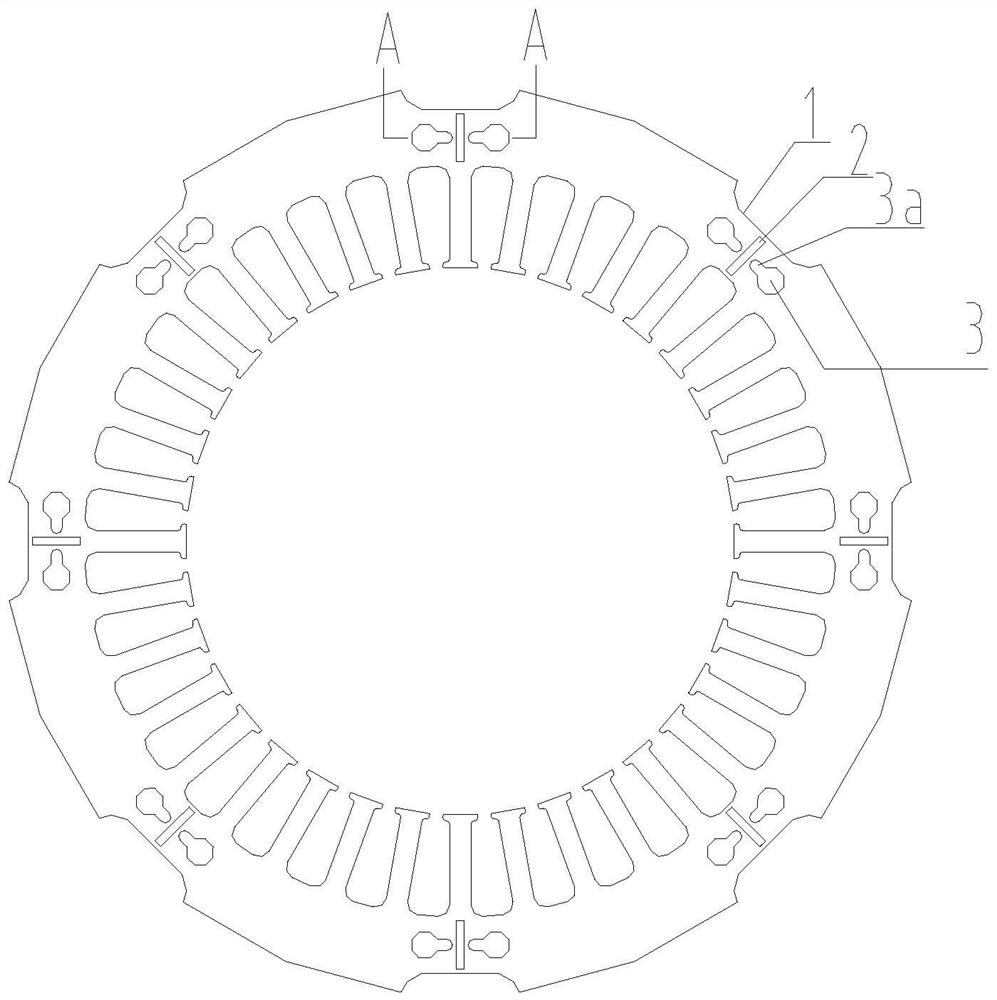
[0029] Such as figure 1 and figure 2 As shown, one embodiment of the motor stator of the present inventio...


PUM


Abstract

The invention provides a motor stator, a motor and a compressor, the motor stator comprises a plurality of punching sheets which are overlapped and buckled, the edge of each punching sheet is provided with n grooves at intervals, and the opening of each groove faces the outer side of the motor stator, so that a non-contact gap is formed between the motor stator and a motor shell; and a buckling point is correspondingly arranged on the inner side of each groove. The U-shaped groove is formed in the outer circle of the iron core of the motor stator, so that a non-contact gap is formed between the iron core and the motor shell, that is, the motor shell is not in hard contact with the buckling point on the punching sheet through a tangible structure, and therefore extrusion stress generated when the motor stator and the motor shell are assembled through a hot jacket cannot be transmitted to the buckling point, and the reliability of the motor stator is improved. Therefore, the buckling points are not loosened or deformed, the stability of the overall structure of the stator is ensured, and the fit clearance between the inner circle of the stator core and the rotor is kept.

Description

Technical field [0001] The present invention relates to the field of motors, and in particular, to a motor stator, a motor, and a compressor. Background technique [0002] The assembly of the stator and housing of the existing compressor motor is based on the overference fit of the thermal sleeve. The hot sleeve is extruded to the stator core, and since the deduction point position is close to the outer wall of the core, the buckle point and electricity Hard contact between the housing, no anti-deformed structure, the extrusion stress causes the buckle point to generate loose and deformation, resulting in the overall deformation of the stator. The stator deformation causes the mating gap between the inner circles between the stator core and the rotor, that is, the size of the gap in different positions. [0003] This structure has the following disadvantages: 1. Make noise exceeds the standard; 2. Since the stator deformation is necessarily caused by a partial punch, increase the...

Claims


Application Information

Patent Timeline
Patent Type & Authority Applications(China)
IPC IPC(8): H02K1/12H02K1/20H02K5/24
CPCH02K1/12H02K1/20H02K5/24H02K2201/03H02K2213/03
Inventor 李斌楠周丹杨晓琴王大号孙玥肖仁
Owner GREE ELECTRIC APPLIANCES INC
Why Eureka
Try Eureka