
Design method of multi-focus metasurface based on orbital angular momentum of vortex light beam

A technology of orbital angular momentum and vortex beams, which is applied in the micro-nano field, can solve the problems of limited application space and functions, the inability to realize the control of vortex light carrying angular momentum, and limited metasurface design methods, and achieve the effect of improving performance

Active Publication Date: 2022-03-25
INST OF PHYSICS - CHINESE ACAD OF SCI
View PDF3 Cites 1 Cited by
  • Summary
  • Abstract
  • Description
  • Claims
  • Application Information

AI Technical Summary

Problems solved by technology

However, the traditional optical imaging system is limited by the principle that it cannot realize the regulation of the vortex light carrying angular momentum, especially the decoding of specific orbital angular momentum in multiple channels.
At the same time, the current research based on the combination of metasurfaces and orbital angular momentum mostly achieves pattern imaging, which greatly limits the application space and functions of this powerful control method.
For the important zooming function in optics, the current design methods of metasurfaces are limited, and there is no design method to realize zooming by using the orbital angular momentum carried in the light field.

Method used


Image

  • Design method of multi-focus metasurface based on orbital angular momentum of vortex light beam
  • Design method of multi-focus metasurface based on orbital angular momentum of vortex light beam
  • Design method of multi-focus metasurface based on orbital angular momentum of vortex light beam

Examples


Embodiment Construction

[0029] Those skilled in the art will be more aware of the above and other objects, advantages and features of the present invention according to the following detailed description of specific embodiments of the present invention in conjunction with the accompanying drawings.

[0030] Apparently, the embodiments described with reference to the drawings are only some exemplary embodiments, and it should be understood that the present application can also be implemented in other forms and should not be limited by the embodiments described here. On the contrary, these embodiments are provided to enable a more thorough understanding of the method and principle of the present application, and to fully convey the scope of the method of the present application to those skilled in the art. Unless defined otherwise, technical and scientific terms used herein have the meanings commonly understood by those skilled in the art.

[0031] Before elaborating the technical solution of the inven...


PUM


Abstract

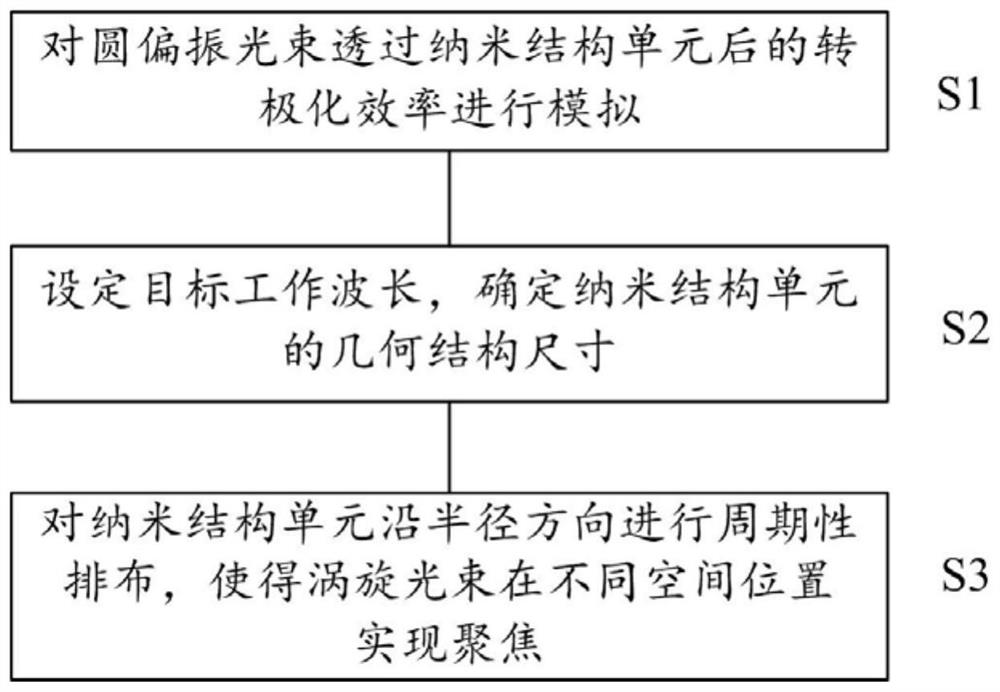
The invention provides a multi-focus metasurface design method based on vortex beam orbital angular momentum and an imaging device. According to one embodiment, the design method comprises the following steps: simulating the polarization conversion efficiency of a circularly polarized light beam after the circularly polarized light beam penetrates through a nano-structure unit; a target working wavelength is set, the geometric structure size of a nanostructure unit is determined, and the polarization conversion efficiency of the nanostructure unit on the circularly polarized light beam at the target working wavelength is larger than a preset value; and the nanostructure units are periodically arranged in the radius direction, and the circular polarization vortex light beam carrying the orbital angular momentum is focused at different spatial positions by combining an additional geometric phase achieved by rotating the nanostructure unit at each position around the center of the nanostructure unit. According to the method, the focusing of the incident light at different spatial positions can be realized, so that the defect that zooming is realized by depending on mechanical displacement to control the position change of the lens in a traditional optical imaging system is overcome.

Description

technical field [0001] The present application relates to the field of micro-nano technology, in particular, to a design method for realizing a multi-focus metasurface by utilizing orbital angular momentum and a three-dimensional integrated multi-focus or zoom metasurface device obtained according to the design method. Background technique [0002] The traditional macroscopic optical focusing system requires cooperation between lens groups and relies on the overall surface geometric curvature of each lens to realize the deflection modulation of the beam, such as focusing, polarization selection, phase regulation or dispersion composite light and other functions. Metasurface is a new type of optical material developed by researchers in recent years, which refers to an artificial structural material with periodic or non-periodic sub-wavelength unit structures arranged in a certain way and capable of regulating electromagnetic waves. The research results show that artificially ...

Claims


Application Information

Patent Timeline
Patent Type & Authority Applications(China)
IPC IPC(8): G02B27/00
CPCG02B27/0012
Inventor 李俊杰顾长志郑睿瑄耿广州杜硕潘如豪金爱子
Owner INST OF PHYSICS - CHINESE ACAD OF SCI
Learn More