
Ammonia mixing test device for automobile exhaust system

A technology of automobile exhaust system and test device, which is applied in the direction of measuring device, vehicle test, machine/structural component test, etc. It can solve the problems of destroying internal flow field, destroying product structure, low efficiency, etc., and achieves good measurement effect , Improve measurement efficiency and high measurement accuracy

Pending Publication Date: 2022-03-25
保定市屹马汽车配件制造有限公司
View PDF0 Cites 0 Cited by
  • Summary
  • Abstract
  • Description
  • Claims
  • Application Information

AI Technical Summary

Problems solved by technology

[0004] First, part of the product structure behind the catalytic converter is removed, and then a mechanical arm is used to control the measuring head to perform point-by-point measurement on the end face of the catalytic converter. This method seriously damages the product structure, resulting in relatively large deviations in measurement results
[0005] Second, a probe is arranged at each measuring point inside the catalytic converter, and then recorded. This scheme seriously damages the internal flow field, and the result deviation is large, which is not advisable.
[0006] Third, manual switching of the measuring head has less impact on the internal flow field and does not damage the product structure. However, every time the position of the measuring head is changed, it must be stopped and restarted. The efficiency is extremely low, and each start will cause the original discharge Inconsistent, resulting in large deviations in measurement results

Method used


Image

  • Ammonia mixing test device for automobile exhaust system
  • Ammonia mixing test device for automobile exhaust system
  • Ammonia mixing test device for automobile exhaust system

Examples


Embodiment 1

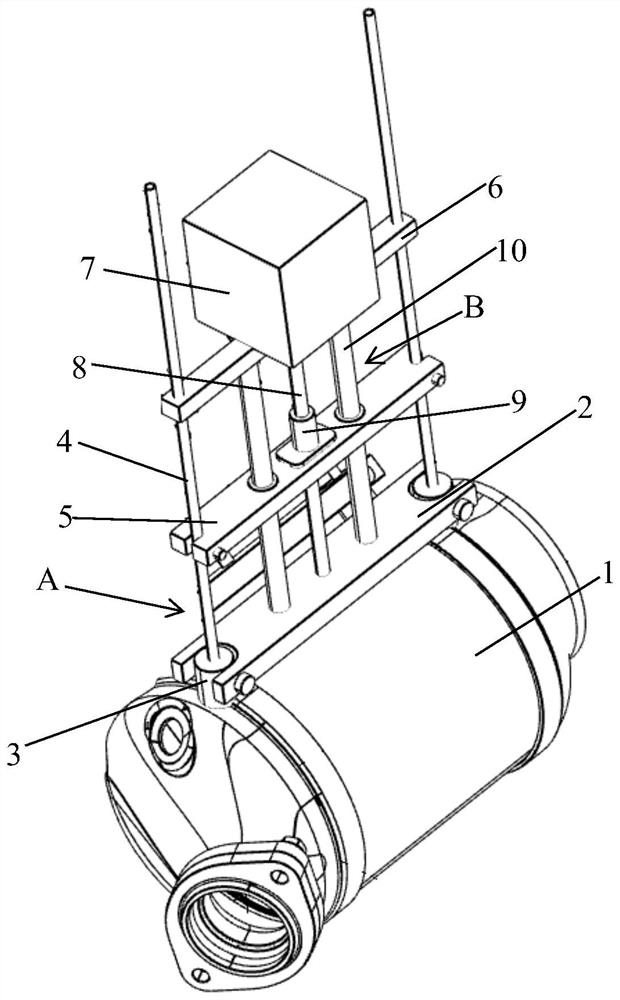
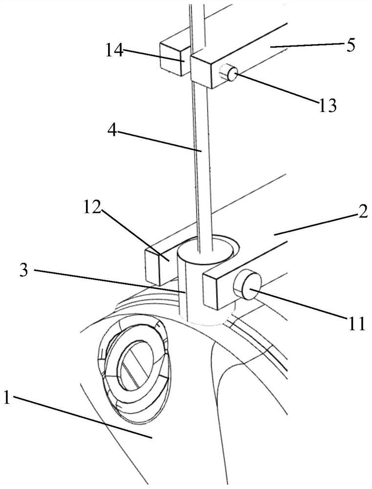
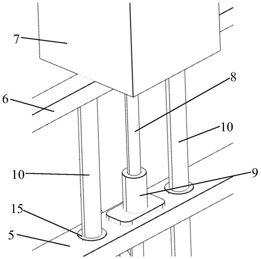
[0045] Such as Figure 1-3 As shown, this embodiment discloses an ammonia mixing test device for an automobile exhaust system. The device to be tested is a catalytic converter 1. The catalytic converter 1 has an air inlet and an exhaust port, and includes: a flexible base 2, an outer surface of the catalytic converter 1 There is a group of air-taking parts 3 on the surface, and there are two air-taking parts 3, which are arranged close to the air inlet and exhaust port of the catalytic converter 1 respectively; the air-taking parts 3 are provided with gas-taking channels up and down, and the gas-taking channels extend downwards Until it communicates with the inner cavity of the catalytic converter 1; the two ends of the flexible base 2 are respectively fixed and detachable connected with the two air-taking parts 3; One-to-one correspondence of channels; synchronous connecting rod 5, which is located above the flexible base 2, and its two ends are respectively fixedly connected...

Embodiment 2

[0054] Such as Figure 4 As shown, this embodiment adopts two sets of air extraction equipment. Compared with Embodiment 1, the air inlet and the air outlet can be simultaneously taken from two positions at the same time, which improves the efficiency and realizes an exhaust operation at the same time. The difference The air inlet and air outlet under the position take air at the same time.


PUM


Abstract

The invention discloses an ammonia mixing test device for an automobile exhaust system. The ammonia mixing test device comprises a flexible base, a gas taking pipe, a synchronous connecting rod, a motor base, a servo motor, a guide optical axis and a gas detection mechanism. The air taking pipe is driven to move along the air taking channel in a servo motor and lead screw transmission mode, so that the air taking pipe moves to a preset air taking point to achieve the purpose of air taking detection; each group of gas taking pipes are simultaneously driven by the synchronous connecting rod, the same group of gas taking pipes at the gas inlet and the gas outlet of the to-be-measured catalyst can realize simultaneous gas taking under one-time exhaust operation, the to-be-measured catalyst has no structural damage except the additional gas taking piece, the measurement effect is good, the measurement precision is high, and the measurement efficiency is greatly improved.

Description

technical field [0001] The invention relates to the technical field of automobile testing equipment, in particular to an ammonia mixing testing device for an automobile exhaust system. Background technique [0002] In my country, due to the high sulfur content of diesel oil, SCR technology is considered to be the most feasible post-treatment technology for NOx emission control of heavy-duty diesel engines because of its good sulfur resistance. As large cities take the lead in implementing the National IV emission regulations, more and more passenger cars equipped with SCR after-treatment systems have appeared in China. There is an important evaluation parameter in the SCR structure--ammonia distribution (ammonia mixing), ammonia Uneven mixing will seriously affect the performance of the product, which will lead to unqualified discharge and the failure of product calibration. [0003] During the research process, it was found that the results of ammonia mixing at this stage ...

Claims


Application Information

Patent Timeline
IPC IPC(8): G01M17/007G01N33/00
CPCG01M17/007G01N33/0054
Inventor 史涛李帅李立彦董占勇刘少卿
Owner 保定市屹马汽车配件制造有限公司
Learn More