Ice making module and ice maker
An ice mold and ice bucket technology, applied in ice making, ice making, ice storage/distribution, etc., can solve the problems of pressure fluctuation in the refrigeration chamber, abnormal noise, breaking dynamic balance, etc., to achieve high manufacturing efficiency, product economy, The effect of a low number of parts
- Summary
- Abstract
- Description
- Claims
- Application Information
AI Technical Summary
Problems solved by technology
Method used
Image

Examples
Embodiment 1
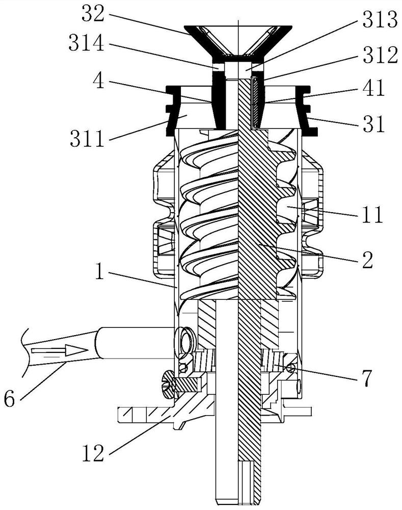
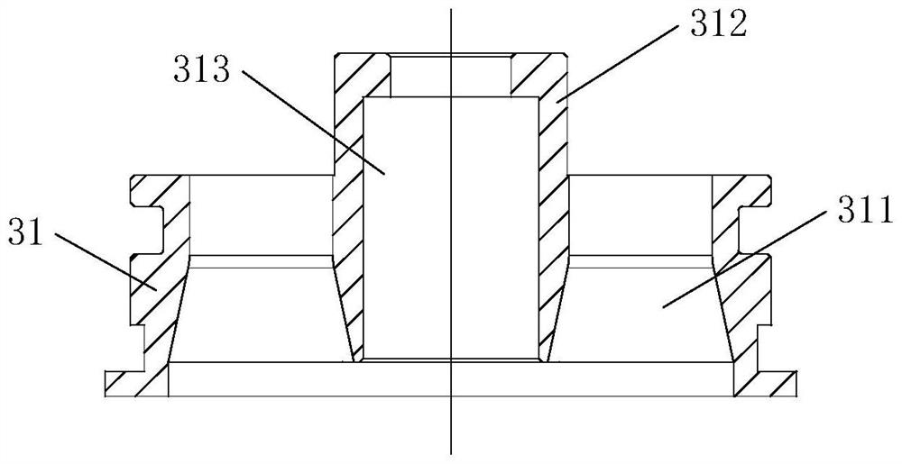
[0062] like figure 2 As shown, the ice squeezing part 31 and the ice folding part are split structures. like figure 2 and image 3 As shown, the upper end surface of the ice-squeezing component 31 is non-planar, and the middle portion protrudes upwards to form a raised portion 312 , and the ice outlet holes 311 are arranged around the raised portion 312 . The ice squeezing part 31 has an ice outlet hole 311 disposed around the raised portion 312 . The ice outlet hole 311 passes through the upper end surface and the lower end surface of the ice squeezing member 31 . The lower end surface of the ice-squeezing part 31 is combined with the upper end surface of the ice-making bucket 1, so that the lower end of the ice outlet hole 311 communicates with the ice-making cavity 11 of the ice-making bucket 1, and the ice in the ice-making cavity 11 can enter and exit through extrusion. Ice hole 311, see figure 1 . continue to combine image 3 , the middle part of the ice squeezi...
Embodiment 2
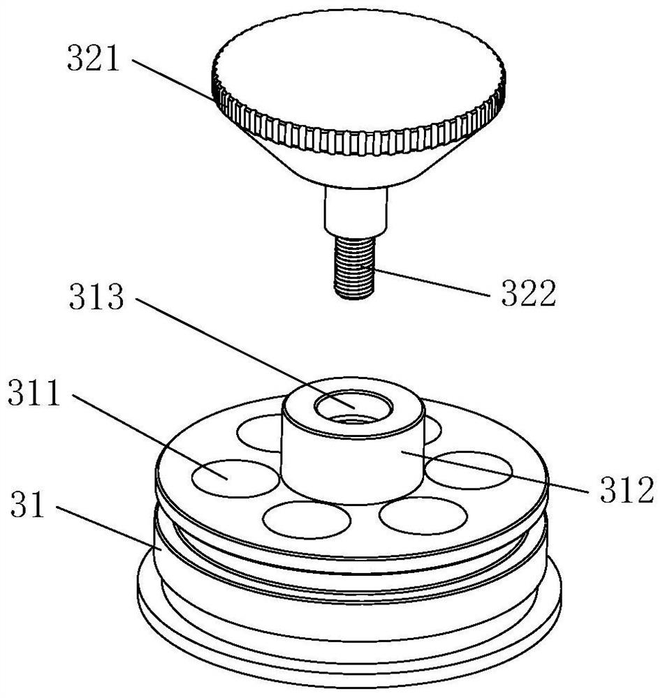
[0065] like Figure 4 and Figure 5 As shown, the ice squeezing part 31 and the ice folding part 32 are integrated. The upper surface of the ice-squeezing part 31 is non-planar, and the middle portion protrudes upwards to form a raised portion 312 , and the ice outlet holes 311 are arranged around the raised portion 312 . The ice-folding component 32 can be integrally formed on the protrusion 312 of the ice-squeezing component 31 . The central portion of the ice squeezing member 31 has a mounting hole 313 passing through its lower end surface and extending into the raised portion 312 . A through hole 314 communicating with the mounting hole 313 is defined on a side wall of the protruding portion 312 . The upper end of the ice scraping rod 2 is installed in the lower part of the mounting hole 313 through the bushing 4 . The upper part of the installation hole 313 communicates with the outside through the through hole 314 , and the upper part of the installation hole 313 and...
Embodiment 3
[0067] like Image 6 and Figure 7 As shown, the ice squeezing part 31 and the ice folding part 32 are integrated. The upper end surface of the ice squeezing part 31 is non-planar, and the middle part of the upper end surface protrudes upwards to form a raised portion 312 , and the ice outlet holes 311 are arranged around the raised portion 312 . The ice-folding component 32 can be integrally formed on the protrusion 312 of the ice-squeezing component 31 . The middle part of the ice squeezing part 31 has a mounting hole 313 passing through its lower end surface and the top surface of the protrusion 312 , and the mounting hole 313 extends upwards and penetrates to the top surface of the ice folding part 32 to communicate with the outside world. The upper end of the ice scraping rod 2 is installed in the lower part of the mounting hole 313 through the bushing 4 . The upper portion of the mounting hole 313 forms a gas passage. That is, the difference between the structure of ...
PUM
 Abstract
Description
Claims
Application Information
 - R&D
- Intellectual Property
- Life Sciences
- Materials
- Tech Scout
- Unparalleled Data Quality
- Higher Quality Content
- 60% Fewer Hallucinations
Browse by: Latest US Patents, China's latest patents, Technical Efficacy Thesaurus, Application Domain, Technology Topic, Popular Technical Reports.
© 2025 PatSnap. All rights reserved.Legal|Privacy policy|Modern Slavery Act Transparency Statement|Sitemap|About US| Contact US: help@patsnap.com