
Intelligent spot welding rubber support

A rubber bearing and spot welding technology, which is applied to bridge parts, bridges, buildings, etc., can solve the problems of single detection information, high cost, and difficulty in monitoring the force of the bearing, and achieve the effect of comprehensive detection information and convenient operation.

Pending Publication Date: 2022-03-25
GUANGXI UNIV
View PDF0 Cites 0 Cited by
  • Summary
  • Abstract
  • Description
  • Claims
  • Application Information

AI Technical Summary

Problems solved by technology

[0003] In the prior art, due to the integral shape of the finished support, it is difficult to monitor the force of the support. Even if there are some support using the sensing unit, the detected information is relatively simple. At the same time, the support of this kind of support The sensing unit is usually fixed to the support body or buried inside the support. If the sensing unit is to be replaced, the entire support needs to be replaced, which is costly and complicated to operate. Therefore, the present invention proposes an intelligent rubber support To solve the problems existing in the prior art

Method used


Image

  • Intelligent spot welding rubber support
  • Intelligent spot welding rubber support
  • Intelligent spot welding rubber support

Examples


Embodiment 1

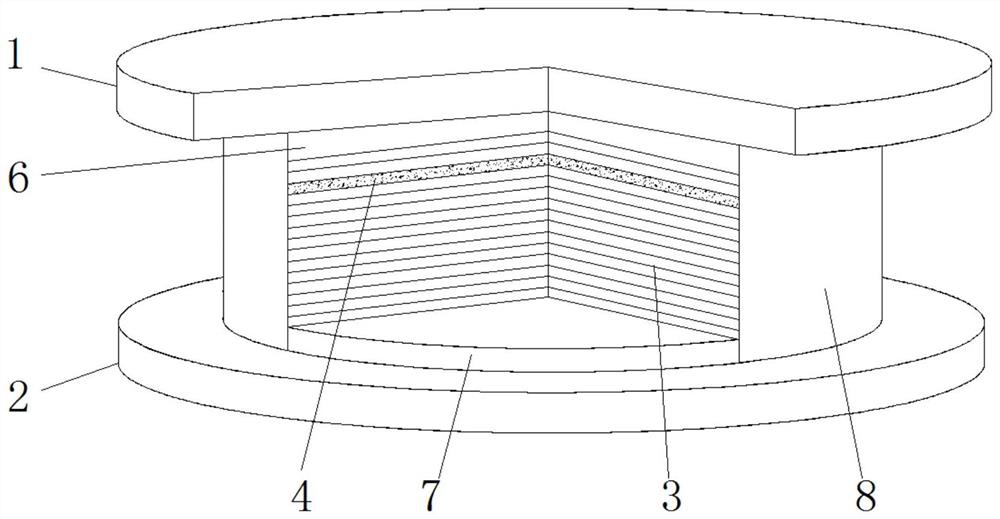
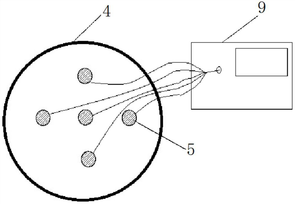
[0033] refer to Figure 1-5 , the present invention provides a spot welding intelligent rubber bearing, comprising a rubber bearing 3, an upper connecting steel plate 1, a lower connecting steel plate 2, several spot welding strain gauge sensors 5, and a protective layer rubber 8;

[0034] The top and the bottom of the rubber bearing 3 are respectively provided with an upper sealing plate 6 and a lower sealing plate 7, and the rubber bearing 3 is provided with several rubber plates and steel plates 4 arranged between the rubber plates; the rubber bearing 3 is composed of several rubber plates. Plates are superimposed, and the steel plate 4 is installed between several rubber plates;

[0035] The upper connecting steel plate 1 is fixedly connected to the upper sealing plate 6, and the lower connecting steel plate 2 is fixedly connected to the lower sealing plate 7;

[0036] Several spot welding strain gauge sensors 5 are installed on the steel plate 4;

[0037] The protective...

Embodiment 2

[0049] refer to Figure 6 , the difference between this embodiment and Embodiment 1 is that two steel plates 4 are arranged inside the rubber bearing 3, and the two steel plates 4 are respectively installed in the middle upper section and the middle lower section inside the rubber bearing 3, and the two sets of steel plates 4 are arranged along the The cross section where the midpoint in the height direction of the rubber bearing 3 is located is symmetrically arranged;

[0050] Set up in this way, when the steel plate 4 is set to two, the spot welding intelligent rubber bearing of the present invention is installed in the position where the bridge needs to be supported, and the spot welding strain gauge sensors 5 on the two steel plates 4 are mutually induced, and the force is measured At the same time, the displacement caused by the force can be measured, and the detection information is more comprehensive.

[0051] When the spot welding strain gauge sensor 5 needs to be rep...


PUM


Abstract

The invention discloses a spot welding intelligent rubber support which comprises a rubber support body, an upper connecting steel plate, a lower connecting steel plate, a plurality of spot welding strain gauge sensors and protective layer rubber. An upper sealing plate and a lower sealing plate are arranged at the top and the bottom of the rubber support respectively, and a plurality of rubber plates and steel plates arranged among the rubber plates are arranged in the rubber support. The upper connecting steel plate is fixedly connected with the upper sealing plate, and the lower connecting steel plate is fixedly connected with the lower sealing plate; the spot welding strain gauge sensors are mounted on the steel plate; the rubber support, the upper sealing plate and the lower sealing plate are coated with the protective layer rubber; wherein at least one steel plate is arranged. Force can be measured according to requirements or displacement caused by stress can be measured while the force is measured, detection information is more comprehensive, and disassembly, assembly and operation are convenient.

Description

technical field [0001] The invention relates to the technical field of building components, in particular to a spot welding intelligent rubber bearing. Background technique [0002] The rubber bearing refers to the supporting part used to support the weight of the container or equipment and fix it in a certain position. It also bears the vibration and earthquake load during operation. It is generally used in bridges, buildings and other fields. The structure of the rubber bearing It is mainly composed of lower support plate, pressure-bearing rubber plate, middle steel lining plate, flat slide plate, upper support plate and other components, among which the rubber plate is the core component of the rubber support, which plays the role of pressure bearing, rotation and force transmission . [0003] In the prior art, due to the integral shape of the finished support, it is difficult to monitor the force of the support. Even if there are some support using the sensing unit, the...

Claims


Application Information

Patent Timeline
Patent Type & Authority Applications(China)
IPC IPC(8): E01D19/04
CPCE01D19/042
Inventor 邓年春张振荣宁锋柏琦
Owner GUANGXI UNIV
Learn More