Large-current wire arranging and connecting device
A connection device and high-current technology, which is applied in the field of new energy charging pile wire management, can solve the problems of accelerating wire damage and reducing user experience, and achieves the effect of avoiding wear and simplifying wire transfer operations
- Summary
- Abstract
- Description
- Claims
- Application Information
AI Technical Summary
Problems solved by technology
Method used
Image

Examples
Embodiment 1
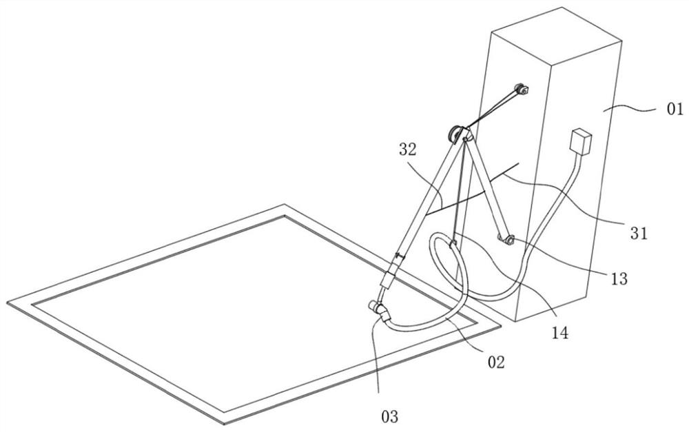
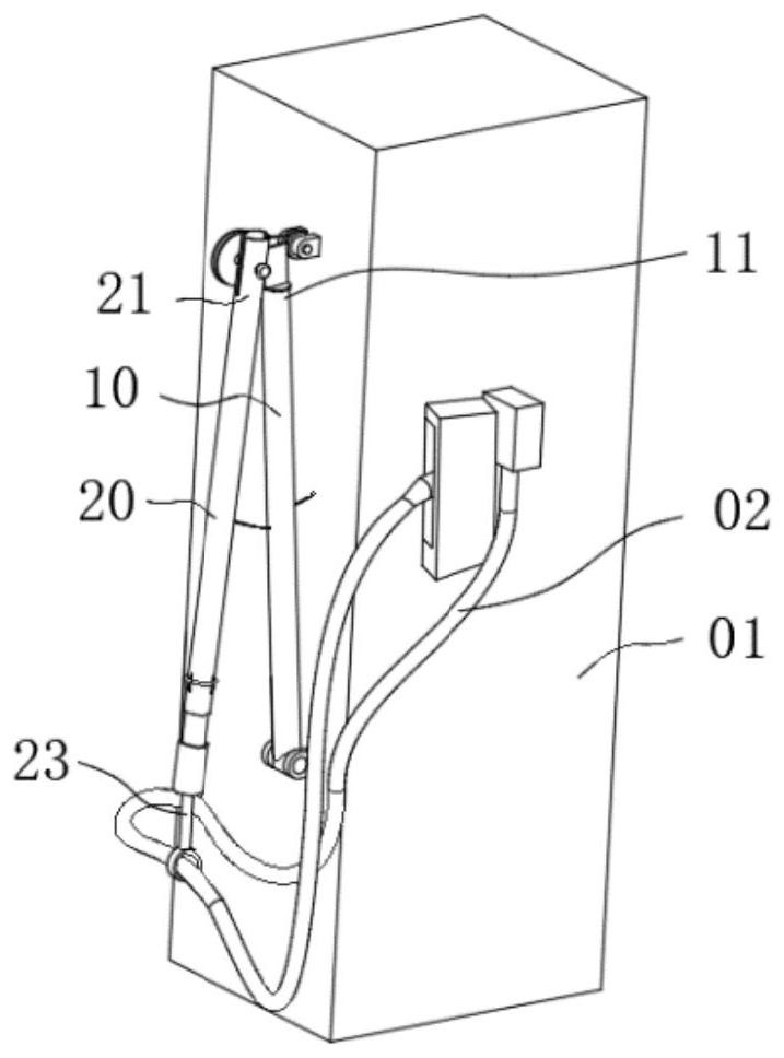
[0061] refer to Figure 1-Figure 20 , the present embodiment provides a large-current wire management connection device, including a first connecting arm 10 and a second connecting arm 20, the first connecting arm 10 and the second connecting arm 20 have a first hinged end 11 and a second hinged end respectively end 21, the first connecting arm 10 and the second connecting arm 20 are hinged to each other through the first hinged end 11 and the second hinged end 21;
[0062] Wherein, the other end of the first connecting arm 10 relative to the first hinged end 11 has a rotating connection part 13 connected to the charging pile 01;
[0063] Wherein, the other end of the second connecting arm 20 opposite to the second hinged end 21 has a charging connection end 23 connected to the large flow wire 02;
[0064] The thick and bulky high-current wires cannot be controlled freely like moving ordinary wires during the movement. It is necessary to hold one end and the middle of the hig...
Embodiment 2
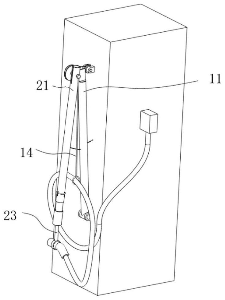
[0074] refer to figure 1 , Figure 3-Figure 6 , this embodiment is proposed on the basis of Embodiment 1, and further, a sling 14 is connected to the articulated position of the first hinged end 11 and the second hinged end 21, and the other end of the sling 14 is used to connect a large current wire of the middle.
[0075] The way that the charging connection part is connected to the middle part of the large-flow wire has avoided the contamination of the large-flow wire due to contact with the ground during the dragging process. However, since the position of the middle part of the high-flow guide end has been restricted by the charging connection end 23, the high-flow wire is relatively thick and hard. When the charging gun 03 is inserted back into the mobile charging pile, a certain deformation and bending of the high-flow wire is required to connect the charging gun. 03 Insert the charging pile back. For some users with relatively weak strength, it may be difficult to co...
Embodiment 3
[0079] refer to Figure 7 , Figure 11 Further, the first hinged end 11 includes a connecting piece 12 and a hinged shaft 121, one side of the connecting piece 12 is connected to the first connecting arm 10; the hinged shaft 121 passes through the connecting piece 12 vertically; and, the axis of the hinged shaft 121 It is perpendicular to the length direction of the first connecting arm 10; and the axis of the hinge shaft 121 does not intersect with the first connecting arm 10;
[0080] The rotation connection between the hinge shaft 121 and the hinge shaft hole 211 makes the first connecting arm 10 and the second connecting arm 20 rotate with each other. The axis of the hinge shaft 121 does not intersect with the first connecting arm 10 , that is, the hinge shaft 121 is not arranged on the first connecting arm 10 .
[0081] A hinge shaft hole 211 is opened on the second hinge end 21, and the hinge shaft 121 is penetrated in the hinge shaft hole 211; and, the shortest distan...
PUM
 Abstract
Description
Claims
Application Information
 - R&D
- Intellectual Property
- Life Sciences
- Materials
- Tech Scout
- Unparalleled Data Quality
- Higher Quality Content
- 60% Fewer Hallucinations
Browse by: Latest US Patents, China's latest patents, Technical Efficacy Thesaurus, Application Domain, Technology Topic, Popular Technical Reports.
© 2025 PatSnap. All rights reserved.Legal|Privacy policy|Modern Slavery Act Transparency Statement|Sitemap|About US| Contact US: help@patsnap.com