
Coding method for digital identification

A digital identification and identification code technology, applied in the field of digital identification, can solve the problems of easy tearing, low code reading efficiency, and falling off of the code spraying label, and achieve the effects of improving product quality control, high reading accuracy, and not easy to wear

Pending Publication Date: 2022-03-25
BEIJING HANGXING MACHINERY MFG CO LTD
View PDF4 Cites 0 Cited by
  • Summary
  • Abstract
  • Description
  • Claims
  • Application Information

AI Technical Summary

Problems solved by technology

[0006] In view of the above analysis, the present invention aims to provide a coding method for digital markings to solve the problems of easy tearing, abrasion, falling off and low reading efficiency of existing coding markings

Method used


Image

  • Coding method for digital identification
  • Coding method for digital identification
  • Coding method for digital identification

Examples


Embodiment 1

[0046] A specific embodiment of the present invention, such as Figure 8-11 As shown, a method for assigning digital identifiers is provided, including the following steps:

[0047] Step S1: detecting the state of the ink drop on the coding printing head 209 through the ink drop observation unit;

[0048] Step S2: Print and verify the identification code on the printed circuit board through the dynamic inkjet unit 8; after the verification of the identification code is completed, the identification code is cured by the ultraviolet curing unit 6 to complete the coding of the printed circuit board;

[0049] Step S3: Step S2 and Step S3 are repeated to complete the coding of multiple printed circuit boards.

[0050] In the step S1, the ink drop observation unit includes: a high-speed synchronous camera and a strobe LED light.

[0051] Further, while the stroboscopic LED lights flicker, the high-speed synchronous camera takes pictures of the ink droplets ejected by the coding pr...

Embodiment 2

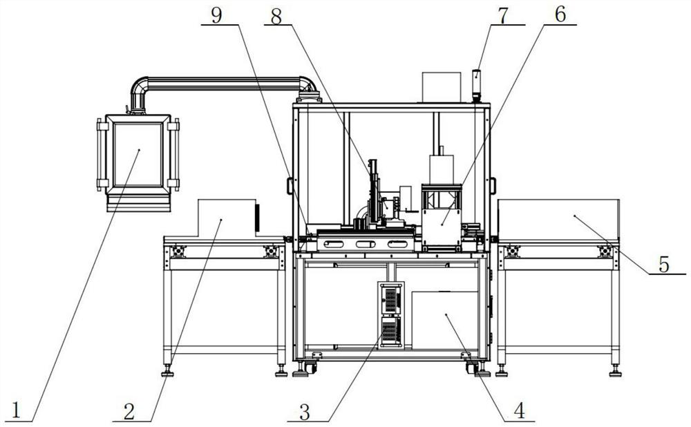
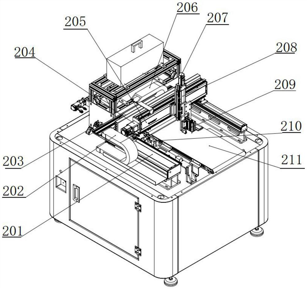
[0078] A specific embodiment of the present invention discloses a coding device for implementing the coding method in Embodiment 1, which is used for coding and marking printed circuit boards. Specifically, such as Figure 1-7 As shown, the coding equipment of the present invention includes: a display screen 1, a feeding mechanism 2, an industrial computer 3, a battery 4, a receiving mechanism 5, an ultraviolet curing unit 6, a warning light 7, a dynamic inkjet unit 8, and a belt transmission mechanism 9.

[0079] In this embodiment, the object to be coded is a printed circuit board. The dynamic inkjet unit 8 is used for spraying ink droplets on the object to be coded to form an identification code, and the identification code is a metal dot matrix pattern.

[0080] Such as figure 1 As shown, the display screen 1 is connected to the casing of the coding device through the cantilever, and the display screen 1 is connected to the cantilever in rotation; the display screen 1 c...


PUM


Abstract

The invention relates to a code assigning method for a digital identifier, belongs to the technical field of digital identifiers, and solves the problems that a code spraying identifier is easy to tear, wear and fall off and the code reading efficiency is low in the prior art. The method comprises the steps that S1, ink droplet state detection is conducted on a tagging printing head through an ink droplet observation unit; s2, carrying out identification code printing and verification on the printed circuit board through a dynamic ink jet unit; after verification of the identification code is completed, the identification code is cured through an ultraviolet curing unit, and code assignment of the printed circuit board is completed; and S3, repeating the step S2 and the step S3 to complete tagging of the plurality of printed circuit boards. According to the invention, automatic tagging of the article is realized.

Description

technical field [0001] The invention relates to the technical field of digital identification, in particular to a coding method for digital identification. Background technique [0002] Almost all standard EMS (Electronic Manufacturing Services) companies and their terminal R&D are managing the process traceability of products. As one of the most important components in the current electronic component industry, printed circuit boards are used in almost all electronic components. On the product, it is called: "the core component of the electronic system". With the increasing quality requirements of printed circuit boards, in order to better realize the quality information control of products in production, information traceability systems such as marking barcodes and QR codes on printed circuit boards have emerged as the times require, and label or ink printing has become Currently the most important identification method. The existing paper labels use non-contact methods ...

Claims


Application Information

Patent Timeline
IPC IPC(8): B41M5/00B41M7/00B41J2/01B41J3/01B41J3/407B41J3/44H05K1/02B41J2/07
CPCB41M5/0047B41M7/0081B41J2/01B41J3/407B41J3/445B41J3/01H05K1/0266B41J2/07Y02P90/30
Inventor 刘晓晨吴凯周松王超
Owner BEIJING HANGXING MACHINERY MFG CO LTD
Learn More