
DC/DC converter and fault-tolerant circuit

A fault-tolerant circuit and fault-tolerant technology, applied in the direction of conversion equipment, electrical components, and output power conversion devices without intermediate conversion to AC, can solve the problems of inability to change control parameters, disappearance of total output voltage, and difficulty in implementing fault-tolerant control. To achieve the effect of saving algorithm debugging work

Pending Publication Date: 2022-03-22
HEFEI UNIV OF TECH
View PDF0 Cites 0 Cited by
  • Summary
  • Abstract
  • Description
  • Claims
  • Application Information

AI Technical Summary

Problems solved by technology

When two DC / DC converters powered in series work, if one DC / DC converter fails to output voltage, the total output voltage will also disappear. In order to ensure the continuity of load power supply, it is necessary to implement fault-tolerant control, that is, one When the DC / DC converter fails, the other converter works technically and keeps the total output voltage unchanged. For digital control, this can be achieved by changing the algorithm. For analog-controlled DC / DC converters, the Control parameters cannot be changed, and fault-tolerant control is difficult to achieve

Method used


Image

  • DC/DC converter and fault-tolerant circuit
  • DC/DC converter and fault-tolerant circuit
  • DC/DC converter and fault-tolerant circuit

Examples


Embodiment Construction

[0054] The specific implementations of the embodiments of the present invention will be described in detail below with reference to the accompanying drawings. It should be understood that the specific implementation manners described herein are only used to illustrate and explain the embodiments of the present invention, and are not used to limit the embodiments of the present invention.

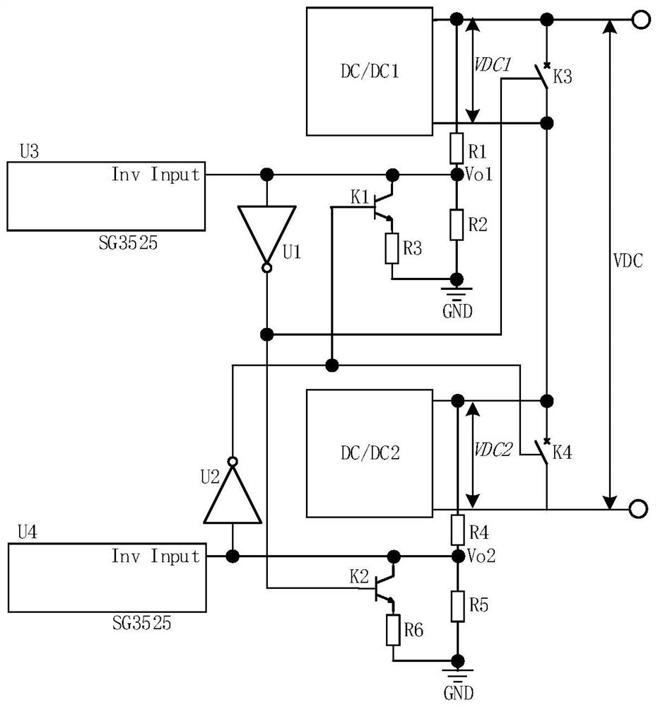
[0055] like figure 1 Shown is a circuit diagram of a fault tolerant circuit in accordance with one embodiment of the present invention. in the figure 1 , the fault tolerance circuit may include a first resistor R1, a second resistor R2, a third resistor R3, a fourth resistor R4, a fifth resistor R5, a sixth resistor R6, a first NOT gate U1, a second NOT gate U2, The first controllable switch K1, the second controllable switch K2, the third controllable switch K3 and the fourth controllable switch K4.

[0056] in the figure 1Among them, one end of the first resistor R1 can be used to conn...


PUM


Abstract

The embodiment of the invention provides a DC / DC converter and a fault tolerance circuit, and belongs to the technical field of DC / DC converter design. The fault tolerance circuit comprises a first resistor and a second resistor, wherein one end of the first resistor is used for being connected to one end of an external DC / DC module; one end of the second resistor is connected with the other end of the first resistor, and the other end of the second resistor is grounded; the input end of the first NOT gate is used for being connected to a control chip of a DC / DC module; one end of the first controllable switch is connected with the input end of the first NOT gate and is connected with one end of the second resistor; one end of the third resistor is connected with the other end of the first controllable switch, and the other end of the third resistor is connected with the other end of the second resistor; one end of the second controllable switch is connected with one end of the first resistor, and the other end of the second controllable switch is used for being connected to the other end of one DC / DC module. According to the DC / DC converter and the fault-tolerant circuit, the stability of the DC / DC converter can be improved under the condition that a control algorithm is not changed.

Description

technical field [0001] The invention relates to the technical field of DC / DC converter design, in particular to a DC / DC converter and a fault tolerance circuit. Background technique [0002] DC / DC converters are commonly used DC conversion devices. When it is necessary to supply power to a larger power load device, it is often necessary to use multiple DC / DC converters in parallel or in series to supply power. When two DC / DC converters powered in series work, if one DC / DC converter fails and does not output voltage, the total output voltage will also disappear. In order to ensure the continuity of load power supply, fault-tolerant control needs to be implemented, that is When the DC / DC converter fails, the other converter technology works and keeps the total output voltage unchanged. For digital control, this can be achieved by changing the algorithm, while for analog-controlled DC / DC converters, its Control parameters cannot be changed, and fault-tolerant control is diffi...

Claims


Application Information

Patent Timeline
Patent Type & Authority Applications(China)
IPC IPC(8): H02M1/32H02M3/04
CPCH02M1/32H02M3/04
Inventor 郑昕昕李宁徐建军田凯
Owner HEFEI UNIV OF TECH
Learn More