Photographic light supplement lamp and light supplement control method

A technology of supplementary light and lamp housing, which is applied in photography, optics, instruments, etc., and can solve problems such as unfavorable clarity, center overexposure, and single light

Pending Publication Date: 2022-03-22
SHENZHEN YONG NUO PHOTOGRAPHIC EQUIP CO LTD
View PDF0 Cites 0 Cited by
  • Summary
  • Abstract
  • Description
  • Claims
  • Application Information

AI Technical Summary

Problems solved by technology

However, the light produced by this method is relatively single, and the center of the light panel is the strongest light, and the farther away from the center area, the edge area, the weaker the light. This situation can easily lead to the center being overexposed and the edge being too dark , not conducive to clear

Method used


Image

  • Photographic light supplement lamp and light supplement control method
  • Photographic light supplement lamp and light supplement control method
  • Photographic light supplement lamp and light supplement control method

Examples


Embodiment 1

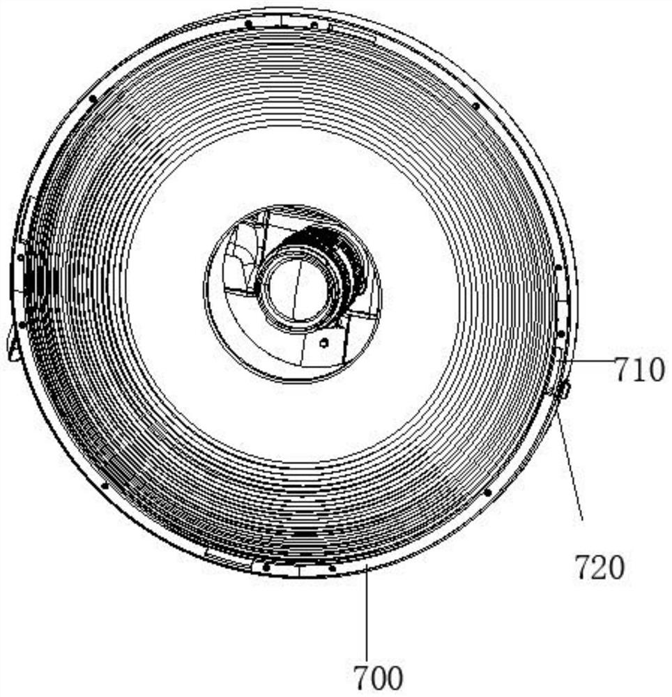
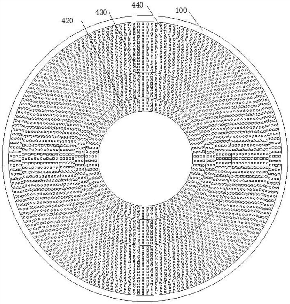
[0045] Embodiment 1 of the present invention discloses a photographic fill light, such as figure 1 , figure 2 as well as image 3 As shown, it includes: a lamp housing 100, a camera bracket 200, a lens 300 and a plurality of lighting boards 400; wherein, the centers of the lamp housing 100, the lens 300 and each of the lighting boards 400 are the same; the lamp housing 100 The center of the lens is provided with a lens through hole 110; the camera bracket 200 is arranged on the back of the lamp housing 100, and the camera bracket 200 is used to connect an external shooting device, and make the optical path of the lens of the external shooting device pass through the The lens through hole 110; the plurality of light boards 400 are arranged on the front of the lamp housing 100; the lens 300 is detachably connected to the edge of the lamp housing 100, and the focal length can be adjusted according to the shooting distance to change the spot size and cover The plurality of ligh...

Embodiment 2

[0067] Embodiment 2 of the present invention also proposes a method for supplementary light control, which is applied to the above-mentioned photographic supplementary light; the method includes:

[0068] Obtain the brightness of multiple shooting areas;

[0069] If there is a shooting area whose brightness does not meet the requirements, then setting the shooting area whose brightness does not meet the requirements as an abnormal area;

[0070] determining the light panel corresponding to the abnormal area;

[0071] The determined light panel is controlled to emit light, so that the brightness of the abnormal area meets requirements.

[0072] In this way, in this way, the light can be supplemented in a targeted manner, which is conducive to generating a clearer image.

[0073] Therefore, the embodiment of the present invention proposes a photographic supplementary light and a method for supplementary light control. The photographic supplementary light includes: a lamp housi...


PUM

PropertyMeasurementUnit
beam angleaaaaaaaaaa

Abstract

The invention provides a photography light supplement lamp and a light supplement control method. The photography light supplement lamp comprises a lamp shell, a camera support, a lens and a plurality of light plates. Wherein the centers of the lamp shell, the lens and the lamplight plates are the same; a lens through hole is formed in the center of the lamp shell; the camera support is arranged on the back face of the lamp shell and used for being connected with external shooting equipment and enabling a lens light path of the external shooting equipment to penetrate through the lens via hole. The light plates are arranged on the front surface of the lamp shell; the lens is detachably connected with the edge of the lamp shell, the focal length can be adjusted according to the shooting distance to change the size of light spots, and a plurality of lamplight plates are covered. According to the scheme, the light-emitting areas are multiple in shape, the situations that in the prior art, the center area is overexposed and the edge area is too dark can be avoided by controlling the lamplight plates, shooting equipment conducts shooting through the lens via hole through the lens via hole, light rays are more uniform, and clearer images can be generated easily.

Description

technical field [0001] The invention relates to the field of photography structures, in particular to a photography supplementary light and a method for supplementary light control. Background technique [0002] At present, there are many types of photography fill lights. In terms of structure, there are panel lights, portable pocket lights, stick lights, down lights, cloth lights, etc., which can meet most shooting scenes; Angle of light, by adding a diffuser, the surface of the etched plastic diffuser produces soft light. However, the light produced by this method is relatively single, and the center of the light panel is the strongest light, and the farther away from the center area, the edge area, the weaker the light. This situation can easily lead to the center being overexposed and the edge being too dark , not conducive to clarity. [0003] Therefore, there is currently a need for a solution to solve the problems in the prior art. Contents of the invention [0...

Claims


Application Information

Patent Timeline
Patent Type & Authority Applications(China)
IPC IPC(8): G03B15/03H05B45/12
CPCG03B15/03H05B45/12
Inventor 庄建南庄永盛邝光盛
Owner SHENZHEN YONG NUO PHOTOGRAPHIC EQUIP CO LTD
Why Eureka
Try Eureka