Radio frequency test probe structure and radio frequency test system

A technology of radio frequency test and test needle, which is applied in the direction of electronic circuit test, measurement of electricity, measurement device, etc., can solve the problems of reducing avoidance space and high characteristic impedance

Active Publication Date: 2022-03-22
HONOR DEVICE CO LTD
View PDF23 Cites 0 Cited by
  • Summary
  • Abstract
  • Description
  • Claims
  • Application Information

AI Technical Summary

Problems solved by technology

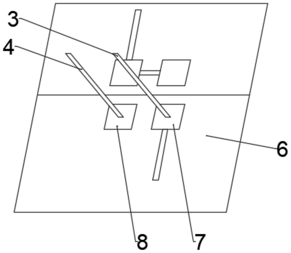
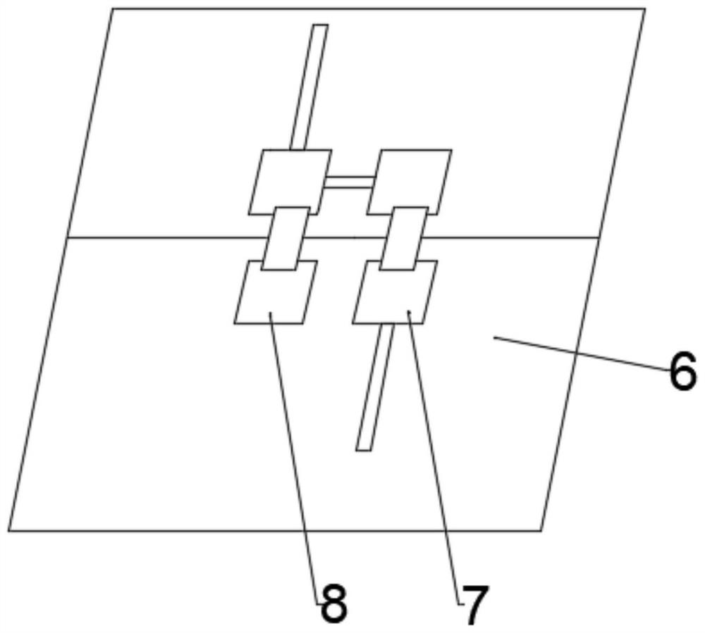
[0004] The embodiment of the present application provides a radio frequency test probe structure and a radio frequency test system, which can solve the problem of high characteristic impedance between the radio frequency test probe and the device under test during the test process, so as to improve the radio frequency signal during the radio frequency test process. Broadband matching while reducing the avoidance space of the structure

Method used


Image

  • Radio frequency test probe structure and radio frequency test system
  • Radio frequency test probe structure and radio frequency test system
  • Radio frequency test probe structure and radio frequency test system

Examples


Embodiment Construction

[0043] The technical solution in this application will be described below with reference to the accompanying drawings.

[0044] In the embodiments of the present application, words such as "exemplary" or "for example" are used as examples, illustrations or illustrations. Any embodiment or design scheme described as "exemplary" or "for example" in the embodiments of the present application shall not be interpreted as being more preferred or more advantageous than other embodiments or design schemes. Rather, the use of words such as "exemplary" or "such as" is intended to present related concepts in a concrete manner.

[0045] In the embodiments of the present application, the terms "first" and "second" are used for description purposes only, and cannot be understood as indicating or implying relative importance or implicitly specifying the quantity of indicated technical features. Thus, a feature defined as "first" and "second" may explicitly or implicitly include one or more ...


PUM


Abstract

The invention provides a radio frequency test probe structure and a radio frequency test system, and relates to the technical field of radio frequency test, and the radio frequency test probe structure comprises a housing, a medium, a first test probe and a second test probe. Wherein the medium is arranged in the shell, the shell is made of a conductive material, the first test needle is arranged in the medium, and the first test needle and the medium are coaxial; the second test pin is arranged on the shell, and the test end of the first test pin and the test end of the second test pin are located at the same end of the shell. An impedance adaptation structure is arranged between the first test needle and the second test needle, and the impedance adaptation structure at least comprises a compensation structure or a coaxial structure. By arranging the compensation structure and / or the coaxial structure, the impedance between the first test pin and the second test pin is close to or equal to the impedance of the radio frequency transmission line, so that the probe structure has better impedance matching in the radio frequency test process.

Description

technical field [0001] The present application relates to the technical field of radio frequency testing, in particular to a radio frequency testing probe structure and a radio frequency testing system. Background technique [0002] During RF testing, general RF testing instruments cannot be directly connected to the device under test, and need to be connected to the product or single board under test through the probe structure, and then the signal is guided to the RF testing instrument. [0003] When testing the PCB board or substrate on the product, the impedance of the RF transmission line is generally 50Ω. It is necessary to match the impedance of the test probe structure with the impedance of the transmission line as much as possible, so that the impedance of the test probe structure is closer to or equal to 50Ω. . In the prior art, one of the solutions is to use a test probe with a coaxial eccentric structure. This solution is limited by the requirements of the chara...

Claims


Application Information

Patent Timeline
Patent Type & Authority Applications(China)
IPC IPC(8): G01R1/067G01R1/073G01R31/28
CPCG01R1/06772G01R1/07307G01R31/2818
Inventor 刘东平翟巍江成
Owner HONOR DEVICE CO LTD
Why Eureka
Try Eureka