
Communication device and method

A technology of communication equipment and communication circuit, which is applied in wireless communication, machine-to-machine/machine-type communication service, service based on location information, etc., and can solve problems such as motion sickness

Pending Publication Date: 2022-03-18
SONY CORP
View PDF0 Cites 0 Cited by
  • Summary
  • Abstract
  • Description
  • Claims
  • Application Information

AI Technical Summary

Problems solved by technology

Any offset / lag can produce the motion sickness normally experienced by VR viewers

Method used


Image

  • Communication device and method
  • Communication device and method
  • Communication device and method

Examples


Embodiment Construction

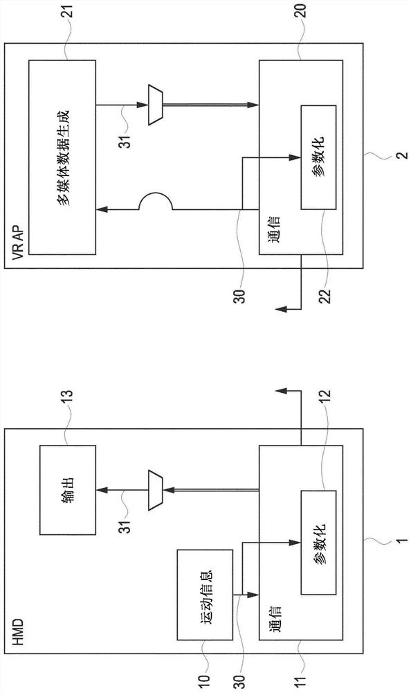
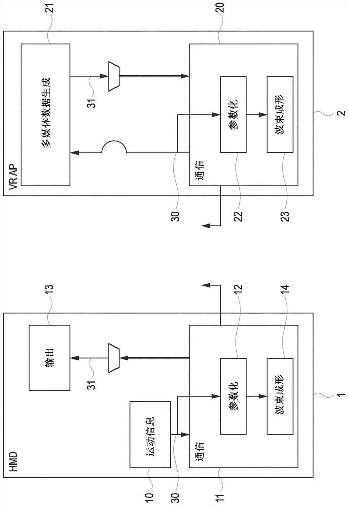
[0036]Virtual reality (VR) applications use head-mounted displays (HMDs). High data rates are sent from the game console to the HMD via a cable such as an HDMI cable. However, cables limit a VR user's range of motion and immersive user experience. Some VR applications provide 6 DOF (6 degrees of freedom), i.e. viewing (and listening to) content does not depend only on orientation, the user views (3 dimensions = degrees of freedom), including pitch, yaw and roll, but also Depends on the position of the HMD (extra three dimensions), ie position and height in the room (x-, y-, and z-coordinates). To account for user motion, data feedback from an integrated IMU (inertial measurement unit) is typically provided via the same cable from the HMD to the console. An IMU typically combines an accelerometer sensor (to detect translational motion) and a gyroscope sensor (to detect rotational changes). A device is represented as 3DOF if the video (or audio) content changes only with resp...


PUM


Abstract

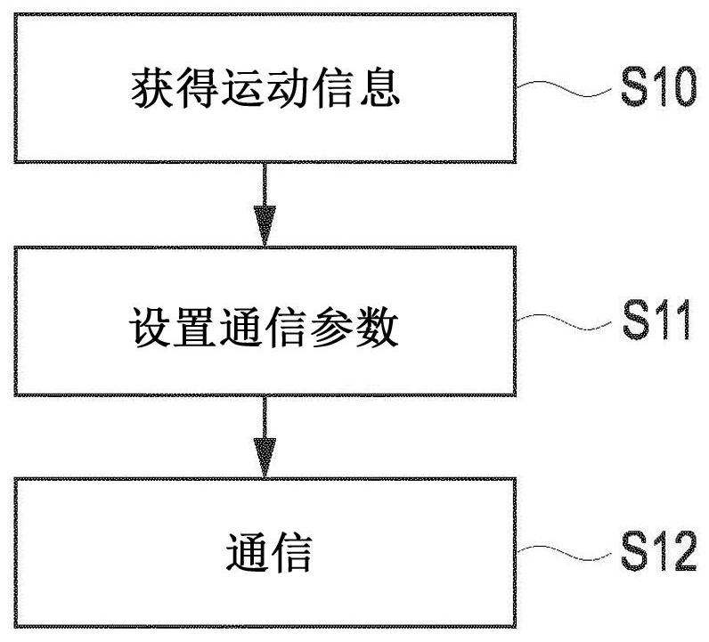
In order to enable fast beam tracking and / or low latency, a first communication device comprises: a motion information circuit configured to obtain motion information representing a motion of the first communication device; a communication circuit configured to communicate with a second communication device; and a parameterization circuit configured to set one or more communication parameters of the communication performed by the communication circuit based on the motion information.

Description

technical field [0001] The present disclosure relates to communication devices and methods, and in particular, to head-mounted displays and virtual, augmented or mixed reality devices, such as video game consoles. Background technique [0002] Wireless communication offers many advantages. For example, communication in the millimeter wave band (eg, 60 GHz for next generation WLAN systems such as IEEE 802.1 lad, ay onwards) offers large bandwidth and low latency once the (analog) beam is established. Initial beam training and subsequent tracking for directional transmission is one of the challenges compared to legacy frequency bands such as 2.4GHz and 5GHz, where unidirectional transmission and reception is possible. This can be even tougher for fast mobile applications such as communication between a virtual reality (VR) headset, also known as a head-mounted display (HMD), and a base station or access point. In the case of a mobile HMD, the initially selected transmit and ...

Claims


Application Information

Patent Timeline
Patent Type & Authority Applications(China)
IPC IPC(8): H04W4/02H04W4/70H04W16/28
CPCH04W4/025H04W4/70H04W16/28H04B7/0695H04B7/0617
Inventor 纳比尔·斯文·洛金费利克斯·费尔豪尔达纳·乔基纳丹尼尔·施奈德
Owner SONY CORP
Learn More