
Sand paving device in road texture depth detection

A technology of texture depth and sand laying, applied in measuring devices, instruments, etc., can solve the problems of inconsistent compactness, easy residual center, large measurement error, etc., to achieve uniform compaction, reduce measurement errors, and ingenious structure.

Pending Publication Date: 2022-03-18
ENG DETECTION & REINFORCING CO LTD OF HENAN PROVINCIAL COMM PLANNING SURVEY & DESIGN INST CO LTD
View PDF0 Cites 0 Cited by
  • Summary
  • Abstract
  • Description
  • Claims
  • Application Information

AI Technical Summary

Problems solved by technology

[0004] In view of the above situation, in order to overcome the defects of the prior art, the present invention provides a sand laying device in the detection of the depth of road texture, which effectively solves the problem of the large circular deviation after paving in the prior art, the floating sand easily remaining in the center, and the sand The density of the edge and center of the circle is inconsistent, resulting in large measurement errors

Method used

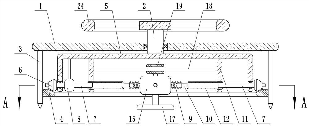
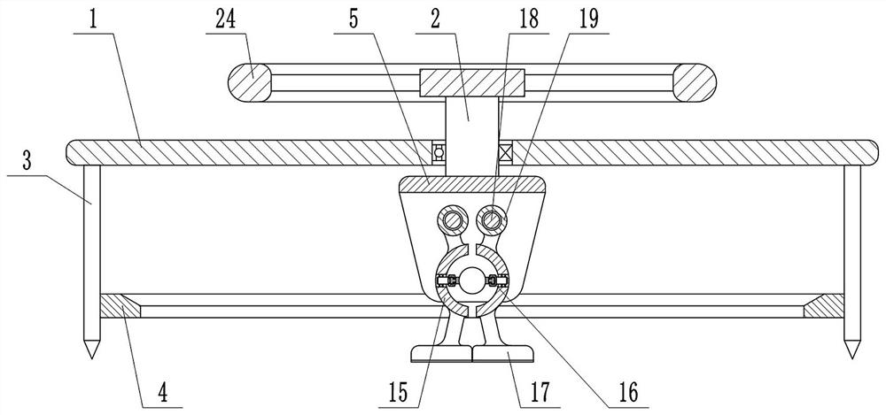

Image

  • Sand paving device in road texture depth detection
  • Sand paving device in road texture depth detection
  • Sand paving device in road texture depth detection

Examples


Embodiment Construction

[0026] The specific implementation manners of the present invention will be further described in detail below in conjunction with the accompanying drawings.

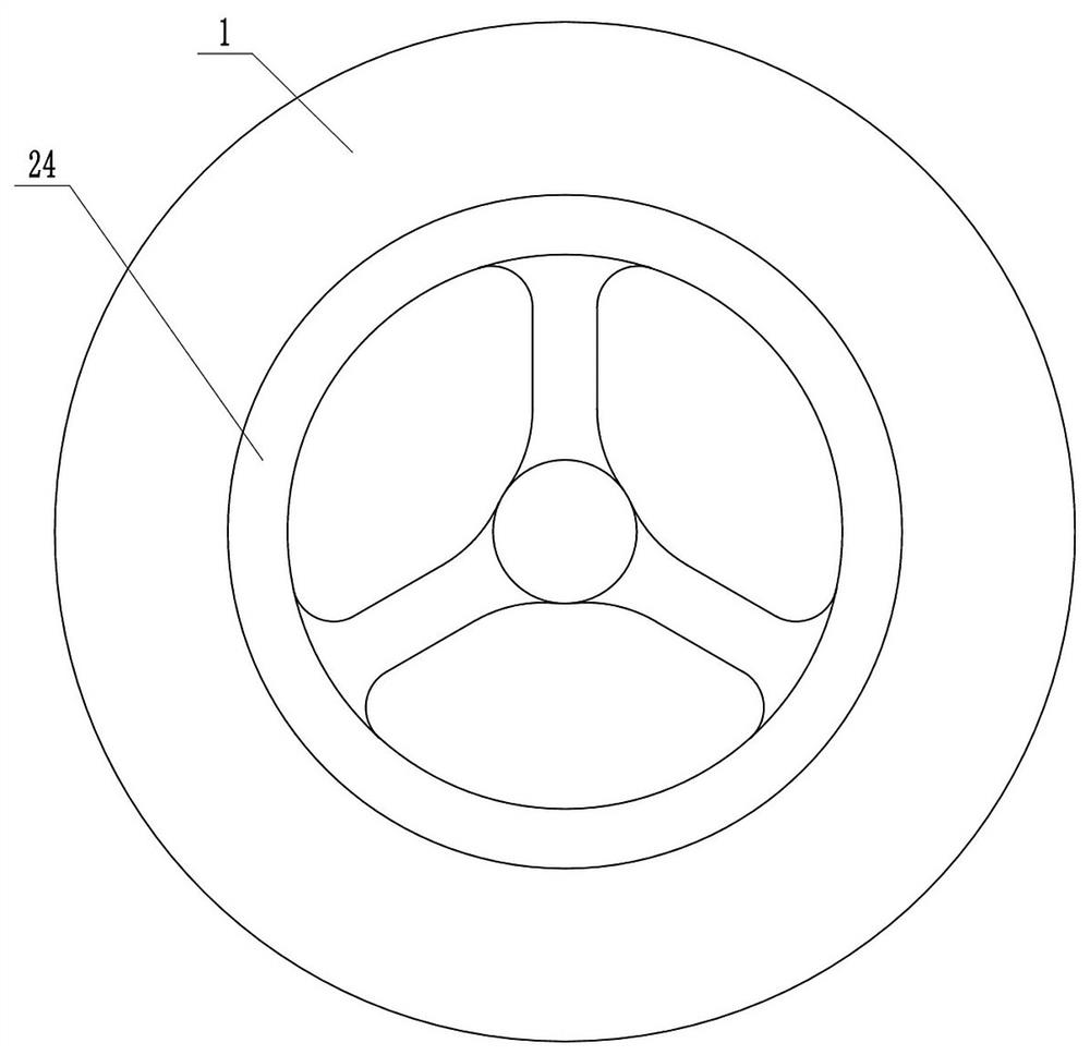
[0027] Depend on Figure 1 to Figure 10 Given, the present invention includes a horizontal flat plate 1, through which a rotating shaft 2 can rotate, and a plurality of vertical and uniformly distributed support rods 3 are fixed on the outside of the lower end of the flat plate 1, and there are horizontal teeth under the flat plate 1. The ring 4 and the outside of the ring gear 4 are fixed to a plurality of support rods 3. There is a U-shaped plate 5 with an opening downward between the ring gear 4 and the flat plate 1. The upper end of the U-shaped plate 5 is fixed with the rotating shaft 2. The side of the U-shaped plate 5 A bevel gear 6 is fixed on the outer side of the lower end of the plate, and the bevel gear 6 meshes with the ring gear 4. There is a spline shaft 7 coaxial with the bevel gear 6 on the inner side of...


PUM


Abstract

The invention provides a sand paving device in road texture depth detection, and effectively solves the problems that after paving, the circle deviation is large, floating sand is easy to remain in the center, and the compactness of the edge of a circle formed by sand and the compactness of the center are inconsistent, so that the measurement error is large. According to the technical scheme, the device comprises a flat plate, a rotating shaft is arranged on the flat plate, a plurality of supporting rods are arranged on the outer side of the lower end of the flat plate, a gear ring is arranged below the flat plate, a U-shaped plate is arranged between the gear ring and the flat plate, bevel gears are arranged on side plates of the U-shaped plate, spline shafts are arranged on the inner side of the U-shaped plate, and a coaxial reverse transmission mechanism is arranged between the left bevel gear and the left spline shaft. Connecting rods are arranged at the two ends of the guide rail, a fixing plate is arranged on one side of each connecting rod, and a spline cylinder is arranged on each fixing plate. The guide rail comprises two threaded steel bars which are the same in screw pitch and opposite in rotation direction, T-shaped sliding rails are arranged on the outer sides of the steel bars, a receding groove is formed in the junction of the T-shaped sliding rails, an arc-shaped block is buckled on the guide rail, a sliding block is hinged in the arc-shaped block, and a T-shaped groove is formed in the sliding block; and a sand pushing plate is fixed on the lower side of each arc-shaped block.

Description

technical field [0001] The invention relates to the technical field of road detection, in particular to a sand laying device for road texture depth detection. Background technique [0002] The manual sand laying method is used to detect the depth of highway pavement structure. The process is: clean the road surface near the measuring point with a broom or brush, and fill the sand cylinder with sand along the side of the cylinder with a small shovel. , measure the top of the sand cylinder with your hand, tap lightly on the hard road surface 3 times to make the sand dense, then use a steel ruler to level it once, pour the sand on the road surface, and finally use a push plate to form a spiral form from the inside to the outside Do the paving movement until the sand spreads into a circle, and no floating residual sand should be left on the surface, and then use a steel ruler to measure the diameters of the two perpendicular directions of the formed circle. [0003] In the actu...

Claims


Application Information

Patent Timeline
IPC IPC(8): G01B21/18
CPCG01B21/18
Inventor 李旭瑞史守强刘晨胡晶冯翔杜沛靳言歌王冕简捷彭文逵周立园孙亚朋全祖花
Owner ENG DETECTION & REINFORCING CO LTD OF HENAN PROVINCIAL COMM PLANNING SURVEY & DESIGN INST CO LTD
Learn More