
Hydraulic control system of safety stop valve

A technology of hydraulic control system and safety cut-off valve, which is applied in the direction of fluid pressure actuation system safety, fluid pressure actuation device, servo motor, etc. It can solve the problems of electric gate valves being unable to move, slow in speed, and not meeting safety requirements, etc., to achieve Fast recovery of fire protection function, convenient and simple operation, high safety effect

Pending Publication Date: 2022-03-18
CHINA PETROLEUM & CHEM CORP +1
View PDF0 Cites 1 Cited by
  • Summary
  • Abstract
  • Description
  • Claims
  • Application Information

AI Technical Summary

Problems solved by technology

At present, manual gate valves or electric gate valves are mostly used as safety valves for entering and exiting tanks in oil depots and tank farms. Manual gate valves require operators to manually rotate the valve operation handwheel. Valves with larger diameters need to be rotated thousands or even tens of thousands of times. Handwheel, the speed is very slow, and the fire situation poses a great threat to the life safety of the operator
[0003] The electric gate valve cannot operate even when the power supply fails
Therefore, manual and electric gate valves cannot meet the rapid shutdown in emergency situations such as accidents and fires, and do not meet the national safety requirements for emergency shutdown of can roots in dangerous places.

Method used


Image

  • Hydraulic control system of safety stop valve
  • Hydraulic control system of safety stop valve
  • Hydraulic control system of safety stop valve

Examples


Embodiment 1

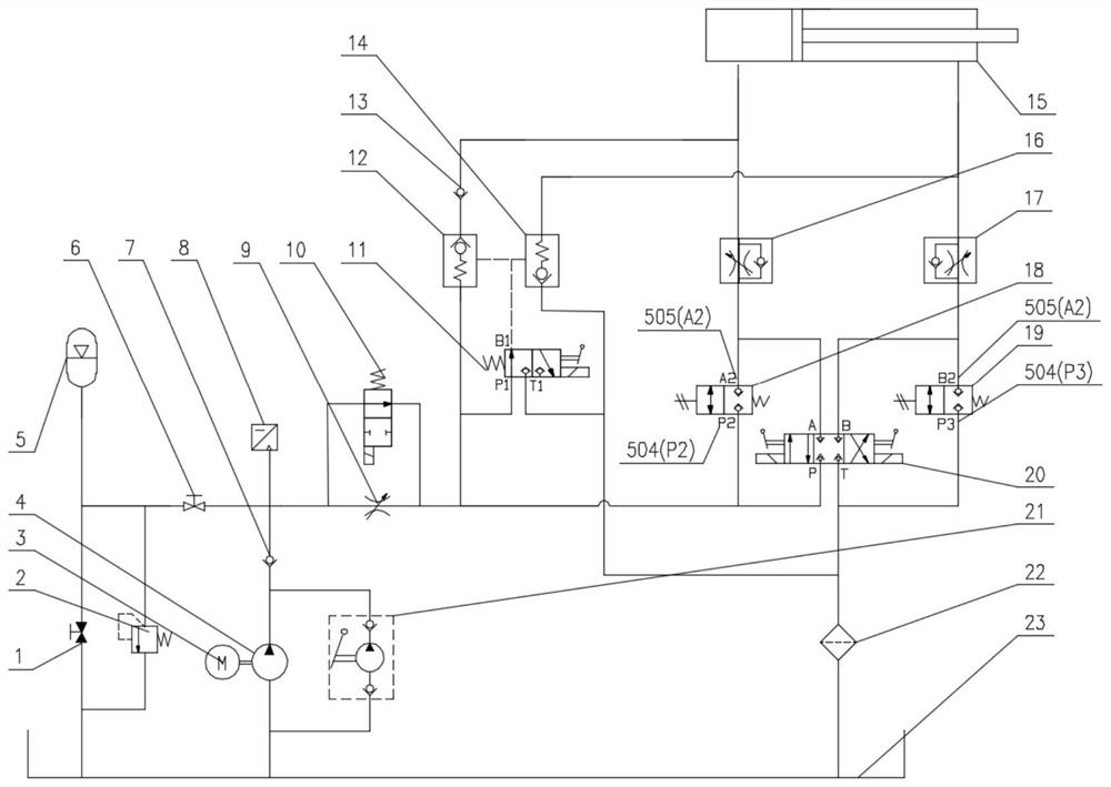
[0030] see figure 1 As shown, the hydraulic control system of the present invention includes an accumulator 5, a first fire damper 18, a second fire damper 19, an oil circuit connected to the upper chamber of the actuator cylinder 5, an oil passage connected to the lower chamber of the actuator cylinder 5, and an oil tank 23 The oil return circuit; wherein: the valve-closing oil circuit is provided with a valve-opening control valve, and the valve-closing control valve is respectively connected with the accumulator, the oil circuit connected to the upper chamber of the executive cylinder, the oil circuit connected to the upper chamber of the executive cylinder, and the The oil circuit of the fuel tank is connected to form a valve-closing oil circuit; the first fire damper is connected in parallel with the valve-closing control valve, and the first fire damper is respectively connected to the accumulator and the oil circuit connected to the upper chamber of the executive oil cyl...

Embodiment 2

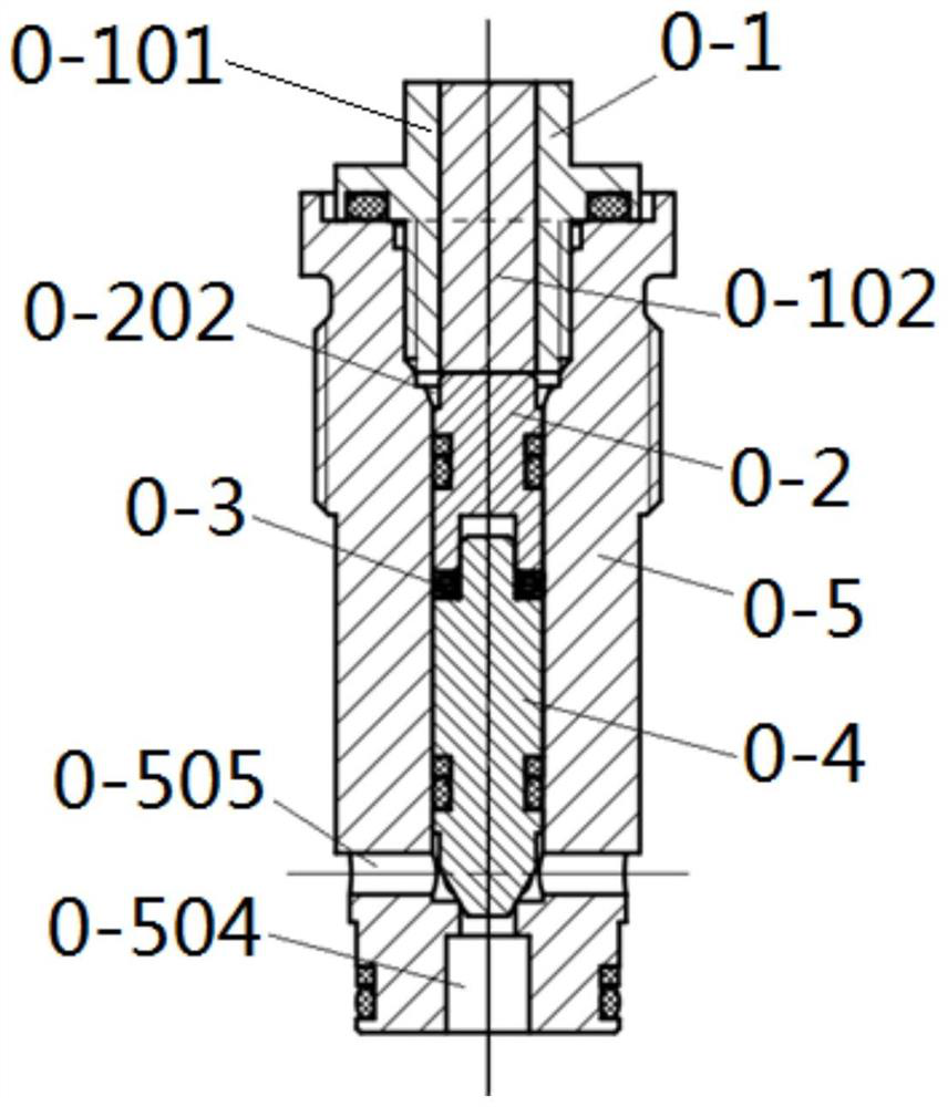
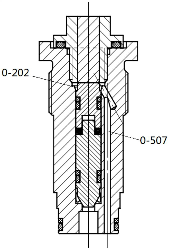
[0039] The first fire damper or / second fire damper of the present invention can be selected from commercially available fire dampers, and in a preferred example, can adopt figure 2 The fire damper shown, the fire damper valve includes fusible plug 0-1, valve body 0-5, valve core 0-4, pressure sleeve 0-2 and spring 0-3; the valve body is provided with a working through hole in the axial direction , one end of the working through hole is used to install the fusible plug, the other end is the medium inlet and outlet 0-504, and the side wall of the medium inlet and outlet is provided with the first inlet and outlet 0-505;

[0040] The valve core, spring and pressure sleeve are sequentially installed in the working through hole along the axial direction, and the fusible plug is installed at one end of the working through hole, pressing the pressure sleeve, spring and valve core in sequence, so that the end of the valve core blocks the medium from entering. The outlet and the first...

Embodiment 3

[0051] In some schemes, the control system of the present invention is provided with an emergency shut-off oil circuit, which is used to shut down the controlled valve in an emergency when the power supply fails. figure 1 As shown, the emergency shutdown oil circuit includes an emergency shutdown solenoid valve 11, a first hydraulic control check valve 12 and a second hydraulic control check valve 14, wherein the emergency shutdown solenoid valve is connected with the accumulator and the first hydraulic control check valve respectively. The pressure guiding port of the check valve, the pressure guiding port of the second hydraulic control check valve are connected to the oil circuit connected to the fuel tank; the first hydraulic control check valve is respectively connected to the accumulator and the oil circuit connected to the upper chamber of the executive cylinder, The second hydraulically controlled one-way valve is respectively connected to the oil return circuit connect...


PUM


Abstract

The invention discloses a hydraulic control system of a safety stop valve. According to the disclosed scheme, an energy accumulator, a first fireproof valve, a second fireproof valve, a valve closing control valve, a valve opening control valve, an oil way connected with an upper cavity of an execution oil cylinder, an oil way connected with a lower cavity of the execution oil cylinder and an oil return way connected with an oil tank are included; all the valves are connected to form a valve opening oil way and a valve closing oil way. The two fireproof release valves are arranged in the oil way of the hydraulic system, the fireproof valves are opened in the case of fire, and the oil way is automatically communicated to achieve valve closing; the fireproof release valve can automatically sense the environment temperature when a fire occurs, the valve can be automatically closed no matter an accident site is powered on or powered off, and once the environment reaches the dangerous temperature, the safety is very high. And the system has an emergency turn-off function, the valve opening and closing functions can be recovered by switching oil ways after emergency turn-off, and meanwhile, the fireproof function can be conveniently and quickly recovered.

Description

technical field [0001] The invention belongs to the technical field of electro-hydraulic actuators and pipeline valves, and relates to a hydraulic drive system for safety cut-off valves, which can be applied to the control of tank root safety valves in oil depots and tank farms, and can be automatically activated in emergency situations such as fire and power failure. off. Background technique [0002] The safety shut-off valves such as the tank root valves that control the roots of oil tanks in oil depots and tank farms are open during daily work, and must be closed in case of emergency such as fire or circuit failure. At present, manual gate valves or electric gate valves are mostly used as safety valves for entering and exiting tanks in oil depots and tank farms. Manual gate valves require operators to manually rotate the valve operation handwheel. Valves with larger diameters need to be rotated thousands or even tens of thousands of times. Handwheel, the speed is very s...

Claims


Application Information

Patent Timeline
Patent Type & Authority Applications(China)
IPC IPC(8): F15B11/08F15B1/02F15B13/02F15B20/00
CPCF15B11/08F15B1/02F15B13/024F15B20/00
Inventor 刘胜蔡婧刘维国王丽然杨春晖王波黄吉伟井健
Owner CHINA PETROLEUM & CHEM CORP
Learn More