
Safety joint and layered water control tubular column

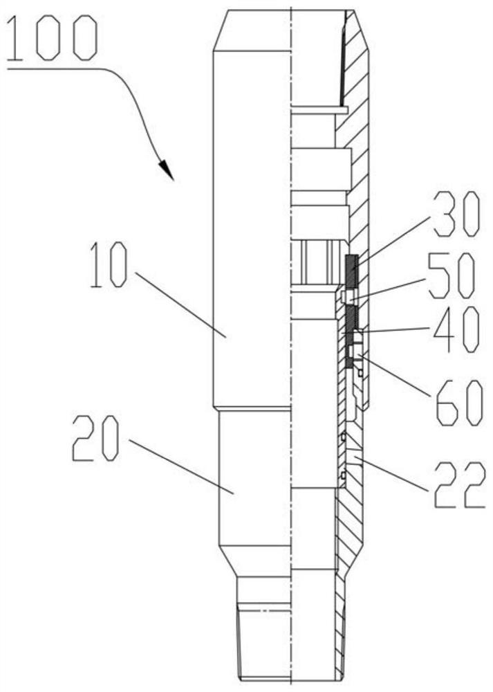
A technology of safety joints and water control pipes, which is applied in drilling pipes, casings, and production fluids, etc., can solve problems such as affecting the salvage effect, complicated operations, and direct shearing of pins, and achieves the effect of facilitating subsequent operations.

Active Publication Date: 2022-03-18
PETROCHINA CO LTD
View PDF5 Cites 0 Cited by
  • Summary
  • Abstract
  • Description
  • Claims
  • Application Information

AI Technical Summary

Problems solved by technology

The pin-type safety joint is convenient for later salvage, but there is a risk of the pin being directly sheared when the pipe string is stressed during running and production
Especially when the layered pipe string needs to be pressed, the pin of the safety joint is directly stressed, and the pin is easily cut off, making the pipe string easy to fall
In addition, if the number of pins is set too much, it will affect the later salvage effect
The claw spring type safety joint avoids the risk of safety joint disengagement during string running and production, but in the later salvage, it needs to be lowered into the pipe string several times for fishing, the operation is complicated and the cost is high

Method used


Image

  • Safety joint and layered water control tubular column
  • Safety joint and layered water control tubular column
  • Safety joint and layered water control tubular column

Examples


Embodiment Construction

[0048] The details of the present invention can be understood more clearly with reference to the accompanying drawings and the description of specific embodiments of the present invention. However, the specific embodiments of the present invention described here are only for the purpose of explaining the present invention, and should not be construed as limiting the present invention in any way. Under the teaching of the present invention, the skilled person can conceive any possible modification based on the present invention, and these should be regarded as belonging to the scope of the present invention.

[0049] It should be noted that when an element is referred to as being “fixed on” or “disposed on” another element, it can be directly on the other element or there may be an intervening element. When an element is referred to as being "connected to" another element, it can be directly connected to the other element or intervening elements may be present.

[0050] The or...


PUM


Abstract

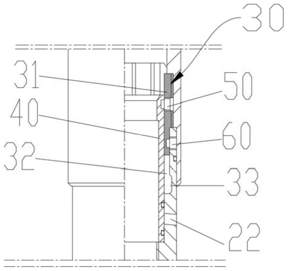
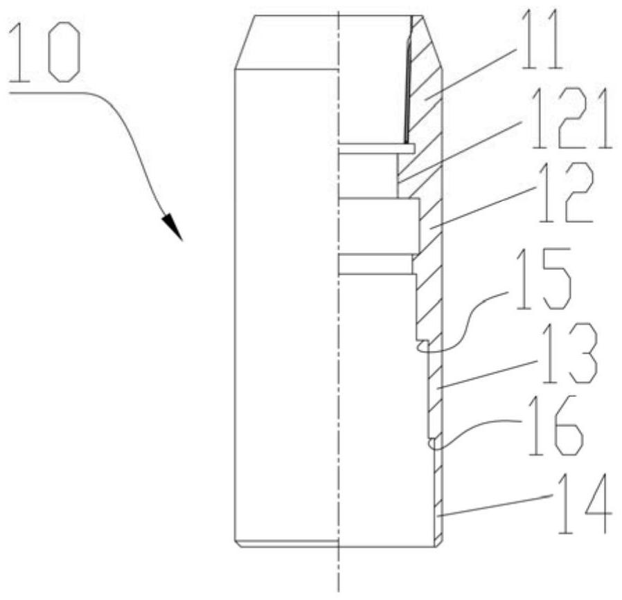
The safety connector comprises an upper connector body, a lower connector body, a pawl spring and an unsealing sleeve, the upper connector body and the lower connector body are both vertically-arranged cylindrical bodies, the lower connector body is hung at the lower end of the upper connector body through the pawl spring, the top end of the pawl spring is a cylindrical connecting part, and the top end of the pawl spring is connected with the upper connector body. The connecting part is arranged in the upper connector body in a penetrating mode and fixedly connected with the upper connector body, a plurality of reeds are arranged at the bottom end of the pawl spring, the reeds are fixedly arranged at the bottom end of the connecting part and evenly distributed in the circumferential direction of the connecting part, the reeds extend into the lower connector body, a clamping groove is formed in the inner wall of the top end of the lower connector body, and the reeds are inserted into the clamping groove in an aligned mode. The unsealing sleeve is cylindrical and penetrates through the pawl spring, the top end of the unsealing sleeve is fixedly connected with the connecting part through a first shear pin, and the bottom end of the unsealing sleeve is in sealing fit with the inner wall of the lower connector body. According to the safety connector and the layered water control tubular column, the safety connector cannot be disengaged in the tripping-in and production process, and the safety connector can be conveniently disconnected when fishing is needed in the later period.

Description

technical field [0001] The invention relates to the field of petroleum exploitation machinery and equipment, in particular to a safety joint and a layered water control string. Background technique [0002] At present, in the field of layered water control and sand control pipe strings for downhole operations in oil and gas fields, the pipe string is usually equipped with multiple safety joints because of the convenience of fishing in minor repair operations in the later stage. Each safety joint corresponds to a layer of sand control screens and is salvaged in stages. There are two main types of existing safety joints, pin type and claw spring type respectively. The pin-type safety joint is convenient for later fishing, but there is a risk of the pin being directly sheared when the pipe string is stressed during running and production. Especially when the layered pipe string needs to be pressed, the pins of the safety joint are directly stressed, and the pins are easily cut...

Claims


Application Information

Patent Timeline
Patent Type & Authority Applications(China)
IPC IPC(8): E21B17/02E21B43/08E21B43/12
CPCE21B17/021E21B43/086E21B43/12
Inventor 韩宗正张建军吴志勇丁晓尹剑峰王磊吴超林健韩汉培孟雪白雪姣徐爽于立江曹群
Owner PETROCHINA CO LTD
Learn More