Eureka AIR delivers breakthrough ideas for toughest innovation challenges, trusted by R&D personnel around the world.

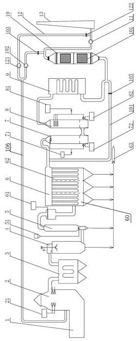
Multi-pollutant collaborative advanced treatment system for hazardous waste incineration flue gas

A technology for incinerating flue gas and hazardous waste, applied in the direction of incinerators, combustion methods, combustion types, etc., can solve the problems of large footprint, shortened service life of catalysts, high emission requirements, etc., achieve safe and reliable operation costs, and reduce NOx The effect of generating and reducing the flue gas temperature

Pending Publication Date: 2022-03-18
SHANGHAI ELECTROMECHANICAL DESIGN & RES INST CO LTD
View PDF0 Cites 1 Cited by
  • Summary
  • Abstract
  • Description
  • Claims
  • Application Information

AI Technical Summary

Problems solved by technology

The denitrification efficiency of SNCR is low, usually 30%-60%. As the emission standards become higher and higher, SNCR can no longer meet the higher emission requirements.
If the "SNCR+SCR" denitrification technology is adopted, the SCR system usually needs to be equipped with GGH (flue gas-flue gas heat exchanger) and SGH (steam-flue gas heat exchanger), and the SCR is usually placed behind the cloth bag, and the flue gas temperature is low. Before entering the SCR, it needs to be heated by SGH. The combined process of "cloth bag + SGH + SCR" is an independent unit, which has problems such as large area, high investment, high catalyst price and short service life (the whole needs to be replaced in 1-3 years). , especially NOx needs to achieve ultra-low emissions (emission concentration below 50mg / Nm 3 ), the service life of the catalyst will be greatly shortened; at the same time, the operating cost will be increased due to factors such as flue gas resistance

Method used


Image

  • Multi-pollutant collaborative advanced treatment system for hazardous waste incineration flue gas

Examples


Embodiment 1

[0038] Hazardous waste is incinerated in the rotary kiln 1, and when the high-temperature flue gas produced enters the secondary combustion chamber 2, ammonia water is injected into the flue gas through the SNCR denitrification device 21 as a denitrification reducing agent, so that the NOx in the flue gas is at 850-1150°C In the temperature window, there is a reduction reaction with ammonia water, and the flue gas after denitrification enters the waste heat boiler 3 for waste heat recovery and cooling. The 550-600°C flue gas discharged from the flue gas outlet of the waste heat boiler 3 enters the quenching tower 4 and cools down to 300°C within 1 second in the quenching tower. Slaked lime is sprayed in the gas as a deacidification agent to remove part of the acid gas. The unreacted deacidification agent is discharged out of the dry deacidification system 5 synchronously with the flue gas, and is synchronized with the ammonia reducing agent sprayed through the ammonia injectio...


PUM


Abstract

The invention discloses a multi-pollutant collaborative advanced treatment system for hazardous waste incineration flue gas. The multi-pollutant collaborative advanced treatment system comprises a secondary combustion chamber (2), a waste heat boiler (3), a quench tower (4), a dry deacidification tower (5), a ceramic fiber filter tube integrated device (6), a washing tower assembly and a fixed bed activated carbon device (10) which are sequentially connected between a rotary kiln (1) and a discharge assembly. A plurality of ceramic fiber filter tubes (62) loaded with denitration catalysts are arranged in the ceramic fiber filter tube integrated device, flue gas is subjected to preliminary deacidification through the dry deacidification tower, is subjected to integrated deacidification, denitration and dust removal through the ceramic fiber filter tube integrated device, is washed and purified through the washing tower assembly, and is discharged after dioxin and heavy metal are deeply removed through the fixed bed activated carbon device. Integrated removal of dust removal, sulfur nitrate and dioxin is achieved based on the ceramic fiber filter tube, secondary deep removal is conducted on heavy metal and dioxin through fixed bed activated carbon, and collaborative deep removal of multiple pollutants in hazardous waste incineration flue gas is achieved.

Description

technical field [0001] The invention relates to a hazardous waste incineration flue gas purification device, in particular to a multi-pollutant cooperative advanced treatment system for hazardous waste incineration flue gas. Background technique [0002] Hazardous waste refers to waste with hazardous characteristics that is included in the national list of hazardous waste or identified according to the national hazardous waste identification standards and identification methods, including incineration disposal residues (such as fly ash, waste gas treatment activated carbon, etc.), organic resin waste, Polychlorinated (brominated) biphenyl wastes, waste organic solvents, medical wastes, etc. Hazardous waste incineration treatment has significant advantages such as harmlessness and volume reduction, and is currently one of the main hazardous waste disposal methods. [0003] At present, most hazardous waste incineration plants use the process of "quick cooling + cloth bag + sc...

Claims


Application Information

Patent Timeline
Patent Type & Authority Applications(China)
IPC IPC(8): B01D53/56B01D53/58B01D53/70B01D53/79B01D53/83B01D53/86F23G7/06B01D50/60B01D53/34B01D53/40
CPCB01D53/56B01D53/79B01D53/343B01D53/83B01D53/40B01D53/8628B01D53/58B01D53/70B01D53/04F23G7/06B01D2251/2062
Inventor 赵开兴邓四化李博房豪杰冯波刘广涛
Owner SHANGHAI ELECTROMECHANICAL DESIGN & RES INST CO LTD
Why Eureka
Eureka Blog
Learn More