
Wire coil rack chuck locking device

A technology of locking device and wire reel frame, which is applied in the directions of transportation and packaging, delivery of filamentous materials, and thin material processing, etc., which can solve the problems of large space required for the overall structure, complicated pneumatic pipelines, and inconvenient installation, etc., to achieve The structure is flexible, precise and stable, the pipe structure is stable, and the structure is stable.

Pending Publication Date: 2022-03-15
HEFEI SMARTER TECH GROUP CORP
View PDF18 Cites 0 Cited by
  • Summary
  • Abstract
  • Description
  • Claims
  • Application Information

AI Technical Summary

Problems solved by technology

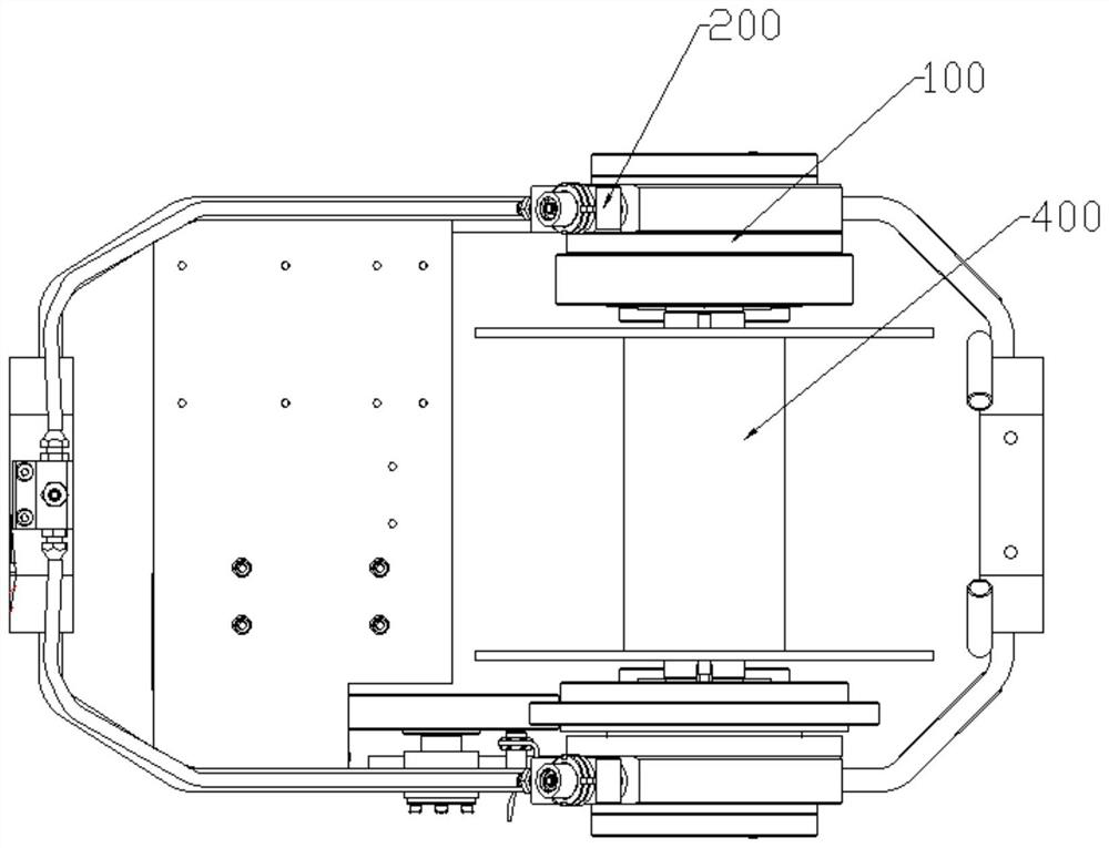
[0002] The wire reel frame is commonly used for winding wires to facilitate storage and transportation of wires. When collecting or unwinding wires, the wire reel frame needs to be clamped and fixed. Due to technological requirements, wire and cable equipment and wire rope equipment are used. The wire reel frame needs to revolve or rotate, and the chuck must be stable and reliable on the rotating body. The existing tubular stranding machine, rope closing machine wire reel frame or similar double-sided spring clamping, pneumatically loosen the clamping structure of the wire reel frame , a pair of cylinders are used to prevent the movement of the clamping shaft for locking protection, but the pneumatic pipeline of this technology is complicated, the installation is inconvenient, and the overall structure requires a large space. Therefore, according to this situation, it is necessary to design a wire reel rack Chuck locking device

Method used


Image

  • Wire coil rack chuck locking device
  • Wire coil rack chuck locking device
  • Wire coil rack chuck locking device

Examples


Embodiment Construction

[0023] The following will clearly and completely describe the technical solutions in the embodiments of the present invention with reference to the accompanying drawings in the embodiments of the present invention. Obviously, the described embodiments are only some, not all, embodiments of the present invention. Based on the embodiments of the present invention, all other embodiments obtained by persons of ordinary skill in the art without making creative efforts belong to the protection scope of the present invention.

[0024] It should be noted that when a component is said to be "fixed" to another component, it can be directly on the other component or there can also be an intervening component. When a component is said to be "connected" to another component, it may be directly connected to the other component or there may be intervening components at the same time. When a component is said to be "set on" another component, it can be set directly on the other component or t...


PUM


Abstract

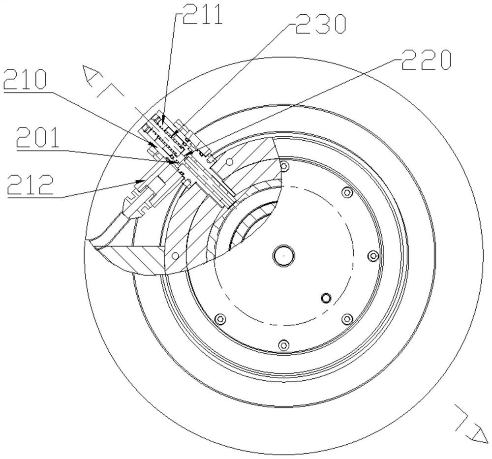
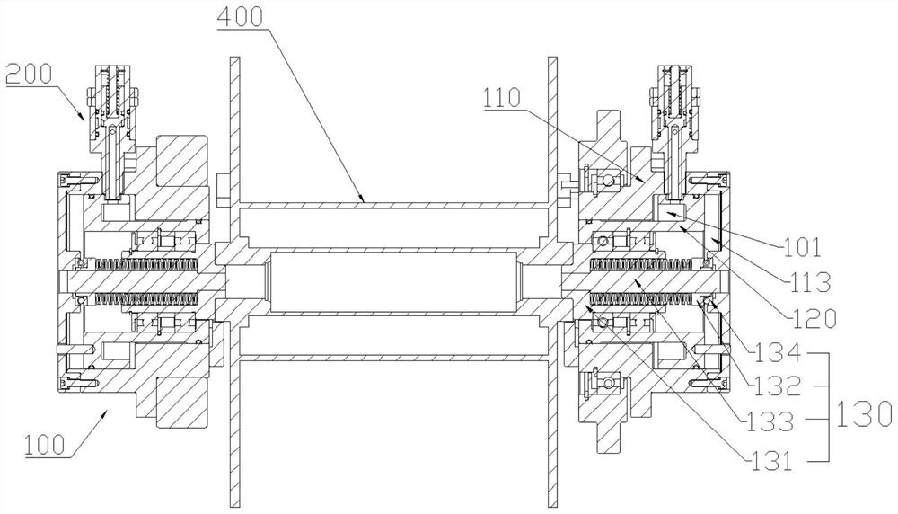
The invention discloses a wire coil rack chuck locking device which comprises a first sleeve body, a second sleeve body, a positioning piece and a first elastic piece. The second sleeve body is located in the first cavity, is matched with the first cavity in shape to form a first auxiliary cavity and can move relative to the first sleeve body along with the change of the pressure intensity in the first auxiliary cavity, the locking structure comprises a valve body, a valve rod and a second elastic piece, and the valve body is provided with a third cavity and an external end; one end of the valve rod penetrates through the first sleeve body and is matched with the notch in position when at the initial position so as to clamp the second sleeve body and block the first hole, and the second elastic piece is constructed to provide supporting force for the valve rod to maintain the initial position. By forming a mechanical pneumatic pipeline, the occupied space of an instrument is saved, on the other hand, the valve rod blocks the first hole while positioning the second sleeve body, the first hole, the second hole, the first auxiliary cavity and the second auxiliary cavity are communicated while positioning is relieved, and structural matching is flexible, precise and stable.

Description

technical field [0001] The invention relates to the technical field of clamping machinery, in particular to a chuck locking device for a wire reel rack. Background technique [0002] The wire reel frame is commonly used for winding wires to facilitate storage and transportation of wires. When collecting or unwinding wires, the wire reel frame needs to be clamped and fixed. Due to technological requirements, wire and cable equipment and wire rope equipment are used. The wire reel frame needs to revolve or rotate, and the chuck must be stable and reliable on the rotating body. The existing tubular stranding machine, rope closing machine wire reel frame or similar double-sided spring clamping, pneumatically loosen the clamping structure of the wire reel frame , a pair of cylinders are used to prevent the movement of the clamping shaft for locking protection, but the pneumatic pipeline of this technology is complicated, the installation is inconvenient, and the overall structure...

Claims


Application Information

Patent Timeline
IPC IPC(8): B65H54/44B65H54/553B65H75/14B65H75/18
CPCB65H54/44B65H54/553B65H75/14B65H75/18B65H2701/34
Inventor 林帅熊盛卫国
Owner HEFEI SMARTER TECH GROUP CORP
Learn More