Protective film roll material punching die
A technology of punching molds and protective films, which is applied in the direction of winding strips, thin material processing, metal processing, etc., and can solve problems such as quality decline, defective products, and tearing
- Summary
- Abstract
- Description
- Claims
- Application Information
AI Technical Summary
Problems solved by technology
Method used
Image
Examples
Embodiment 1
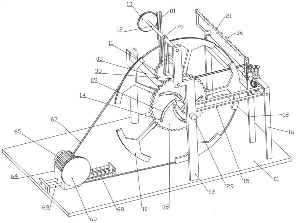
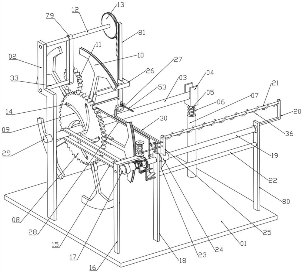
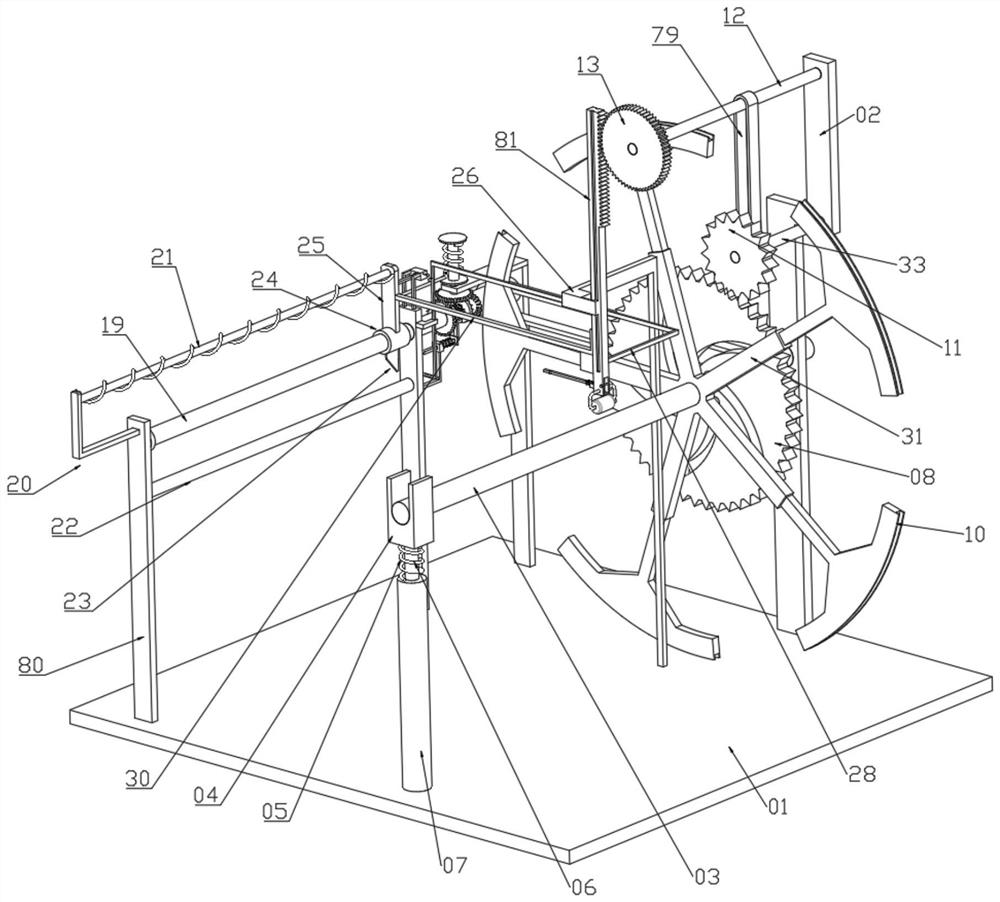
[0032] See Figures 1 to 11 A protective film coil cutting mold comprising the bottom plate 01, fixedly connected to the mounting frame 02 on the bottom plate 01, and the mounting frame 02 is rotated and connected to the pass 29, and the rotary 29 away from one end of the mounting frame 02 is fixed. The rotary roller 03, and the passage 29 fixed to the adjustment mechanism for adjusting the rotational speed of the roller 03, the adjustment mechanism includes a gear disk 08 that is fixed to the passage 29, further comprising fixed connection on the roller 03. The bit support frame 31, the upper limit bracket 31 is slidably connected to the expansion frame 10, and the dilated frame 10 is fixed to one end of the pickup disk 08, and there is a sliding post 14, and the pick-up disk 08 is opened on the pick-up sliding connection tibrus 1 14 adjustment The groove 09 also includes a turn rod 12 that is rotatably coupled to the mounting frame 02, and the rotary rod 12 is fixed from one end ...
Embodiment 2
[0048] See Figure 12 The bonding module includes a diabater 30 fixed to the mounting block 25, the outer wall of the rack 81 is fixedly connected to the mounting rod 70, and the mounting rod is slid on the mounting rod 2 71, the outer wall cover of the pulse post 271 There is a spring 8 72, and the lower end of the pulling post 2 71 is fixedly connected to the heating card ring 73, and the outer wall of the rack 81 is fixed to the side of the rear lever 30, and the mounting lever 2 78 slides on the mounting rod 75. The outer wall of the push rod 75 is fixed to one end of the heating card ring 73, and the push rod 75 is fixed from one end of the triangular push block 74, and the outer wall of the push rod 75 is located at the limit circle 3 77. And the outer wall sleeve between the mounting rod 2 78 is provided with a spring nine 83 for resetting the push rod 75, and the push rod 75 is hinged from one end of the triangular push block 74 to be hinged by a hinge shaft with a diaphrag...
PUM
 Abstract
Description
Claims
Application Information
 - R&D Engineer
- R&D Manager
- IP Professional
- Industry Leading Data Capabilities
- Powerful AI technology
- Patent DNA Extraction
Browse by: Latest US Patents, China's latest patents, Technical Efficacy Thesaurus, Application Domain, Technology Topic, Popular Technical Reports.
© 2024 PatSnap. All rights reserved.Legal|Privacy policy|Modern Slavery Act Transparency Statement|Sitemap|About US| Contact US: help@patsnap.com


