
Opening and closing die and bottom die linkage structure of rotary bottle blowing machine and bottle blowing machine

A technology for opening and closing molds and blowing machines, applied in the field of blowing machines, can solve the problems of difficult processing of the lifting cam track of the bottom mold, wear of the lifting cam track of the bottom mold, large impact force at the moment of contact, etc., and achieves high reliability and high reliability. The effect of saving equipment cost and avoiding impact force

Active Publication Date: 2022-03-15
广东国珠包装机械有限公司
View PDF6 Cites 0 Cited by
  • Summary
  • Abstract
  • Description
  • Claims
  • Application Information

AI Technical Summary

Problems solved by technology

As the running speed of the main engine increases at any time, the precision of the cooperation between the rolling bearing and the lifting cam track of the bottom mold is higher, the processing of the lifting cam track of the bottom mold is more difficult, and the impact force at the moment of contact is greater, which leads to more and more running noise. Long-term high-speed operation, It is easy to cause damage to the rolling bearing or serious wear of the lifting cam track of the bottom mold. In addition, because the bottom mold and the opening and closing mold in the related art operate independently, the coordination between the bottom mold and the opening and closing mold is not good, which easily leads to the blowing mechanism. Incomplete products appear in the finished bottle

Method used


Image

  • Opening and closing die and bottom die linkage structure of rotary bottle blowing machine and bottle blowing machine
  • Opening and closing die and bottom die linkage structure of rotary bottle blowing machine and bottle blowing machine
  • Opening and closing die and bottom die linkage structure of rotary bottle blowing machine and bottle blowing machine

Examples


Embodiment Construction

[0027] In order to facilitate the understanding of the present invention, the present invention will be described more fully below with reference to the associated drawings. Preferred embodiments of the invention are shown in the accompanying drawings. However, the present invention is capable of being implemented in many different forms and is not limited to the embodiments described herein. On the contrary, these embodiments are provided to make the understanding of the disclosure of the present invention more thorough and comprehensive.

[0028] It should be noted that when an element is referred to as being “fixed” to another element, it can be directly on the other element or there can also be an intervening element. When an element is referred to as being "connected to" another element, it can be directly connected to the other element or intervening elements may also be present. The terms "vertical," "horizontal," "left," "right," and similar expressions are used here...


PUM


Abstract

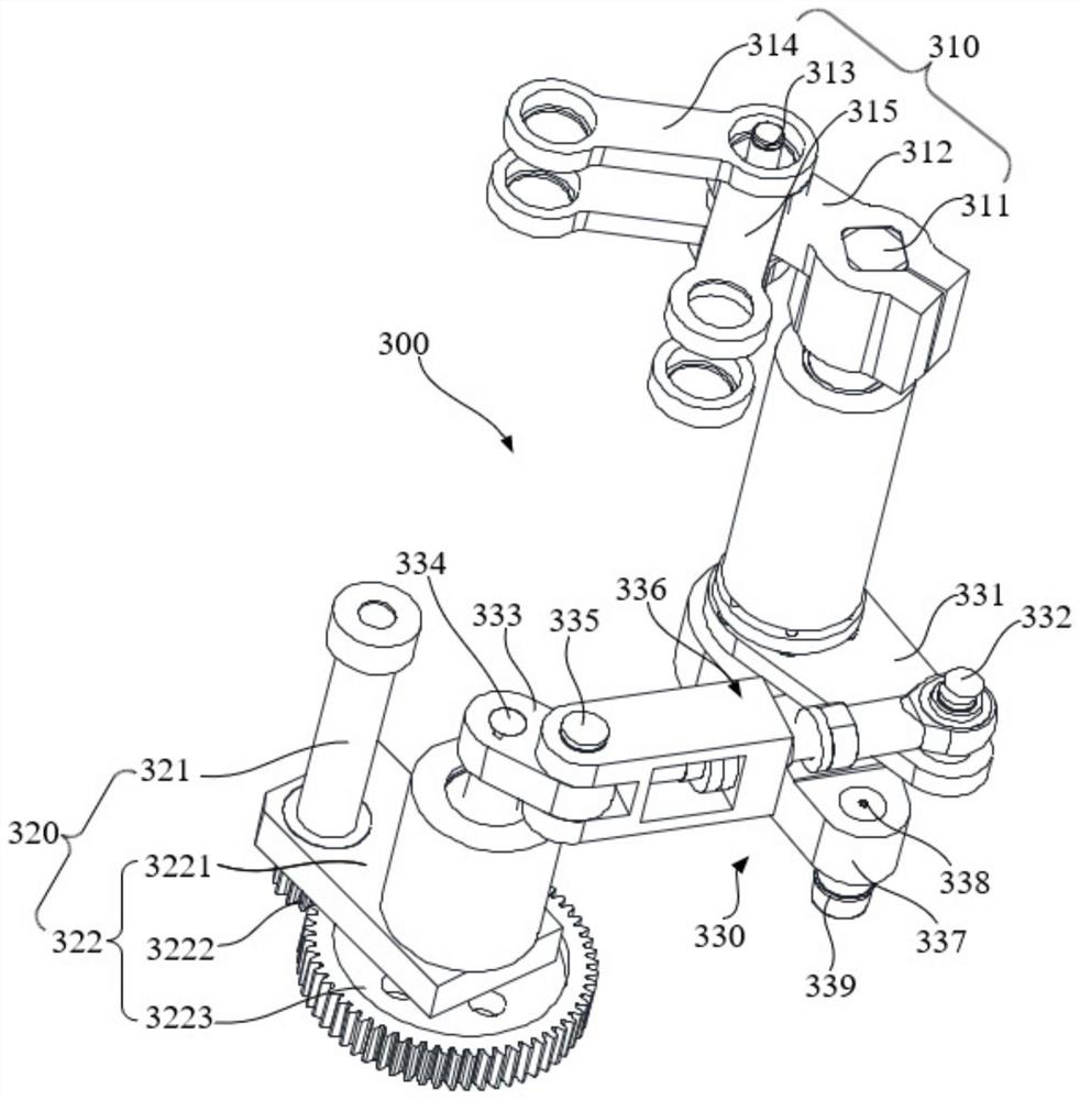
The invention relates to a rotary bottle blowing machine opening and closing mold and bottom mold linkage structure and a bottle blowing machine, the rotary bottle blowing machine opening and closing mold and bottom mold linkage structure comprises an opening and closing module, a bottom module and a linkage device, the opening and closing module has an opening state and a closing state, and the bottom module has a butt joint state in butt joint with the opening and closing module and a separation state in separation from the opening and closing module; the linkage device comprises a connecting rod mechanism in linkage with the opening and closing module, a lead screw mechanism in linkage with the bottom module and a linkage mechanism used for enabling the connecting rod mechanism and the lead screw mechanism to be in linkage, and the connecting rod mechanism can drive the opening and closing module to be switched between the opening state and the closing state. The lead screw mechanism can drive the bottom module to be switched between the butt joint state and the separation state. The linkage mechanism can realize linkage of actions between the connecting rod mechanism and the screw rod mechanism, so that the opening and closing module and the bottom module can be synchronously operated, the matching precision of the opening and closing module and the bottom module is higher, and bottles blown by using the linkage structure are higher in yield, lower in noise and not easy to damage.

Description

technical field [0001] The invention relates to the technical field of bottle blowing machines, in particular to a linkage structure for opening and closing molds and a bottom mold of a rotary bottle blowing machine and a bottle blowing machine. Background technique [0002] The rotary blow molding machine in the related art has multiple blow molding stations, and each blow molding station is composed of an independent mold base, including a bottom mold and an opening and closing mold. Generally, the bottom mold is used to move up and down along the slider, specifically The rolling bearing on the bottom mold is in contact with the lifting cam track of the bottom mold, and the bottom mold realizes lifting motion according to the lifting cam track of the bottom mold. As the running speed of the main engine increases at any time, the precision of the cooperation between the rolling bearing and the lifting cam track of the bottom mold is higher, the processing of the lifting cam...

Claims


Application Information

Patent Timeline
Patent Type & Authority Applications(China)
IPC IPC(8): B29C49/56B29C49/48
CPCB29C49/56B29C49/48
Inventor 李立基雷甜钟声
Owner 广东国珠包装机械有限公司
Learn More