
Gas-liquid separator and fuel cell system

A fuel cell system and gas-liquid separator technology, which is applied to fuel cells, circuits, electrical components, etc., can solve the problems of liquid water freezing, sensor detection accuracy being reduced, liquid water entering the sensor cavity or on the spring diaphragm, etc.

Active Publication Date: 2022-03-11
CHINA AUTOMOTIVE INNOVATION CORP
View PDF11 Cites 3 Cited by
  • Summary
  • Abstract
  • Description
  • Claims
  • Application Information

AI Technical Summary

Problems solved by technology

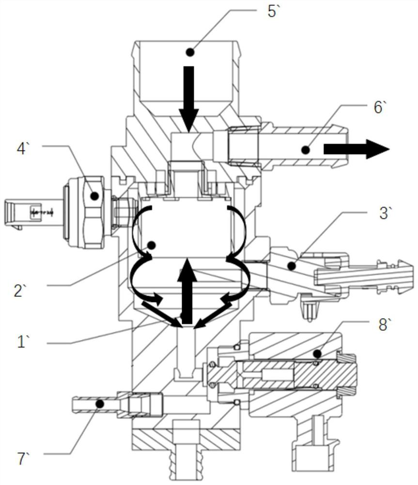
[0003] In existing fuel cell systems, such as figure 1 As shown, the water storage area 1` of the gas-liquid separator is set under the separation chamber 2`, the gas-liquid mixture enters the gas-liquid separator from the mixed gas inlet 5`, the temperature sensor 3` and the pressure sensor 4` are both arranged horizontally, And it is used to monitor the air temperature and air pressure of the separation chamber 2` respectively. The separated gas is discharged from the exhaust port 6`, and the separated water is discharged from the drain port 7`, which is used to control the drain solenoid valve for opening and closing the drain port 7` 8` is located at the lowest point of the gas-liquid separator, and the separated liquid water goes down to the water storage area 1` along the inner wall of the separator, and the water storage area 1` is a cavity structure extending along the vertical direction. In this case, the liquid water accumulated in the water storage area 1` is likely to freeze, which will cause the gas-liquid separator to be blocked and cannot be drained.
Moreover, most of the pressure sensors 4` in the existing gas-liquid separators are arranged horizontally, and it is easy for liquid water to enter the sensor cavity or the spring diaphragm, resulting in a decrease in the detection accuracy of the sensor or direct damage
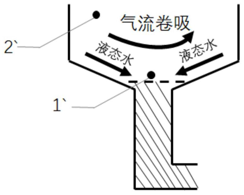
In addition, the separated liquid water is not significantly separated from the separated gas, as figure 2 As shown, during the operation of the gas-liquid separator, there is an air entrainment phenomenon, and a large amount of liquid water will be re-entrained into the gas after separation, reducing the separation efficiency

Method used


Image

  • Gas-liquid separator and fuel cell system
  • Gas-liquid separator and fuel cell system
  • Gas-liquid separator and fuel cell system

Examples


Embodiment Construction

[0043] In order to make the purpose, technical solutions and advantages of the embodiments of the present invention clearer, the technical solutions in the embodiments of the present invention will be clearly and completely described below in conjunction with the drawings in the embodiments of the present invention. Obviously, the described embodiments It is a part of embodiments of the present invention, but not all embodiments. The components of the embodiments of the invention generally described and illustrated in the figures herein may be arranged and designed in a variety of different configurations.

[0044] Accordingly, the following detailed description of the embodiments of the invention provided in the accompanying drawings is not intended to limit the scope of the claimed invention, but merely represents selected embodiments of the invention. Based on the embodiments of the present invention, all other embodiments obtained by persons of ordinary skill in the art wi...


PUM


Abstract

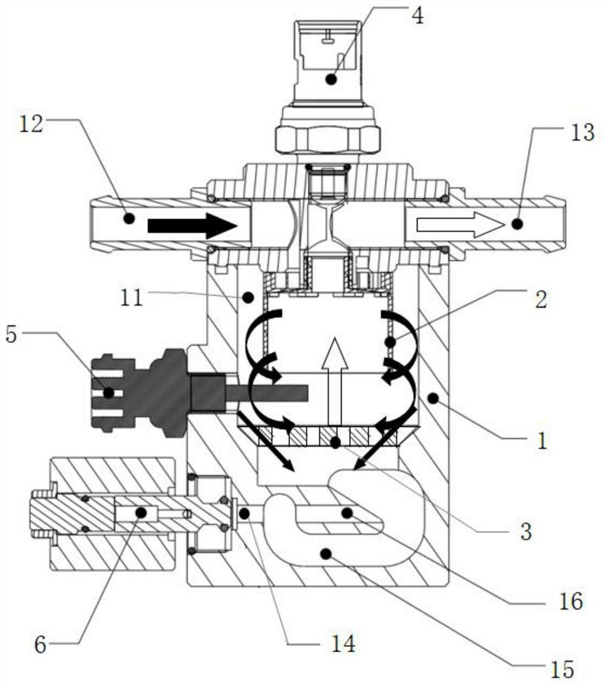
The invention discloses a gas-liquid separator and a fuel cell system, and belongs to the technical field of fuel cells. According to the gas-liquid separator and the fuel cell system, the gas-liquid separator comprises a shell, the shell comprises a separation cavity, a mixed gas inlet, an exhaust port and a water outlet, the mixed gas inlet, the exhaust port and the water outlet are communicated with the separation cavity, the shell further comprises a water storage cavity and an auxiliary flow channel, the water storage cavity comprises a water storage section, a first flow guide section and a second flow guide section, and the water storage section is located below the water outlet; two ends of the diversion section I are respectively connected with the separation cavity and the water storage section, and two ends of the diversion section II are respectively connected with the water storage section and the water outlet; the auxiliary flow channel is located above the water storage section, one end of the auxiliary flow channel is connected with the first flow guide section and the separation cavity, and the other end of the auxiliary flow channel is connected with the second flow guide section and the water outlet. Even if water accumulated in the water storage section is frozen in the low-temperature environment, the water outlet cannot be blocked, newly separated water can flow to the water outlet from the auxiliary flow channel, and the problem that the gas-liquid separator is prone to being blocked in the low-temperature environment and cannot work is solved.

Description

technical field [0001] The invention relates to the technical field of fuel cells, in particular to a gas-liquid separator and a fuel cell system. Background technique [0002] After the fuel cell system is shut down, there is a certain amount of liquid water and high-temperature humid gas in the stack and its pipelines. As the temperature drops and the static time of the system prolongs, condensed water in the gas precipitates and gradually accumulates in the pipelines Flow to the lowest point of the system, and the current mainstream solution is to place the gas-liquid separator at the lowest point of the system, so that the liquid water will eventually flow into the gas-liquid separator, and use the gas-liquid separator to separate the gas-liquid mixture from water. Improve fuel gas utilization. [0003] In existing fuel cell systems, such as figure 1 As shown, the water storage area 1` of the gas-liquid separator is set under the separation chamber 2`, the gas-liquid m...

Claims


Application Information

Patent Timeline
Patent Type & Authority Applications(China)
IPC IPC(8): H01M8/04119H01M8/04746
CPCH01M8/04164H01M8/04776Y02E60/50
Inventor 王英徐勋高盛欢刘松源刘通
Owner CHINA AUTOMOTIVE INNOVATION CORP
Learn More