Rolling shaft limiting and supporting structure for cable saddle of suspension bridge
A technology for supporting structures and suspension bridges, which is applied in bridges, bridge parts, bridge construction, etc., can solve problems such as no effective solutions, and achieve the effect of reducing the cost of molding and reducing the difficulty of molding technology
- Summary
- Abstract
- Description
- Claims
- Application Information
AI Technical Summary
Problems solved by technology
Method used
Image
Examples
Embodiment 1
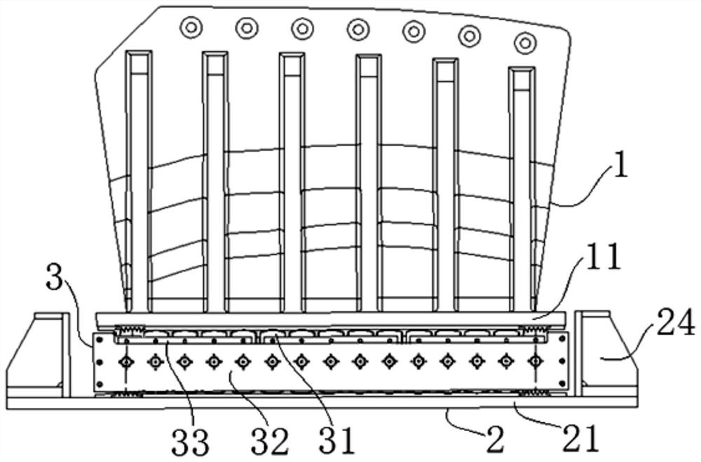
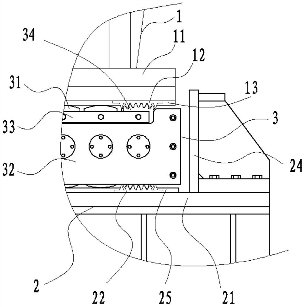
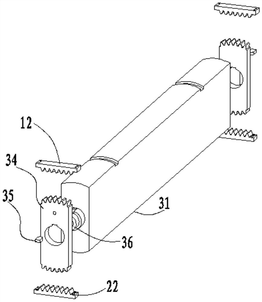
[0035] see figure 1 , figure 2 , image 3 and Figure 4 As shown, the roller type cable saddle of the present invention is a roller type loose cable saddle, which is arranged in an inclined structure (such as Figure 4 As shown, compared with the horizontal plane, it forms an angle of about a° inclination) on the loose cable saddle foundation at the side span in front of the anchor body. The present invention includes a supporting roller assembly 3 arranged between the saddle body 1 and the base 2 .
[0036] The inside of the saddle body 1 has a loose cable saddle groove formed from top to bottom, and the bottom of the saddle body 1 is connected with an upper bearing plate 11 .
[0037] The base 2 is mainly composed of the embedded grid 23 anchored in the concrete tower body, and the lower bearing plate 21 connected to the top of the embedded grid 23 . The longitudinal ends of the lower bearing plate 21 (corresponding to the arrangement direction of the main cables of th...
Embodiment 2
[0057] Other content of this embodiment is the same as Embodiment 1, the difference is:
[0058] The two ends of each roller supporting the roller assembly are respectively connected with toothed stoppers;
[0059] Correspondingly, the saddle side racks of elongated structure are respectively arranged along the longitudinal direction on both lateral sides of the upper bearing plate at the bottom of the saddle body, that is, the saddle side racks on each side are along the longitudinal length of both ends of the upper bearing plate. Direction forming (it can be segmented butt joint or a whole);
[0060] The lateral sides of the lower bearing plate on the top of the base are respectively provided with seat-side racks of elongated structure along the longitudinal direction, that is, the seat-side racks on each side are formed along the length direction of the longitudinal ends of the lower bearing plate (can be divided segment docking, or it can be a whole).
[0061] In this em...
Embodiment 3
[0063] Other content of this embodiment is the same as embodiment 1 or 2, the difference is:
[0064] The tooth-shaped limiter of the supporting roller assembly is only formed with gear teeth in the top area, and the bottom contour is within the coverage of the outer contour of the end surface of the roller;
[0065] Correspondingly, only the bottom of the saddle body is provided with a toothed rack that engages with the tooth-shaped limiter on the support roller assembly, while the lower bearing plate on the top of the base only forms rolling contact with the rollers of the support roller assembly Fitting, gearless transmission fitting structure.
PUM
 Abstract
Description
Claims
Application Information
 - R&D Engineer
- R&D Manager
- IP Professional
- Industry Leading Data Capabilities
- Powerful AI technology
- Patent DNA Extraction
Browse by: Latest US Patents, China's latest patents, Technical Efficacy Thesaurus, Application Domain, Technology Topic, Popular Technical Reports.
© 2024 PatSnap. All rights reserved.Legal|Privacy policy|Modern Slavery Act Transparency Statement|Sitemap|About US| Contact US: help@patsnap.com


