
Water retaining device between quenching machine and quenching furnace and control method of water retaining device

A technology of a water blocking device and a quenching machine, which is used in quenching devices, furnaces, heat treatment furnaces, etc., can solve the problem of inability to adjust the height of the water blocking plate and the waterproof box, pipeline leakage, and the inability to guarantee the lifting of the water blocking plate and the waterproof box, etc. problem, to achieve the effect of convenient rotation and adjustment of the roll

Pending Publication Date: 2022-03-11
BAOSHAN IRON & STEEL CO LTD
View PDF5 Cites 0 Cited by
  • Summary
  • Abstract
  • Description
  • Claims
  • Application Information

AI Technical Summary

Problems solved by technology

Disadvantages of this device: 1) If the pipeline leaks in the fixed hydraulic lift, it will not be able to raise the water retaining plate and the waterproof box; 2) The water retaining plate and the waterproof box have no adjustment mechanism, and the adjustment of the water retaining plate and the waterproof box cannot be adjusted. high

Method used


Image

  • Water retaining device between quenching machine and quenching furnace and control method of water retaining device
  • Water retaining device between quenching machine and quenching furnace and control method of water retaining device
  • Water retaining device between quenching machine and quenching furnace and control method of water retaining device

Examples


Embodiment Construction

[0029] The present invention will be further described below in conjunction with accompanying drawing and specific embodiment:

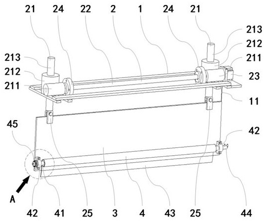
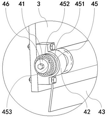
[0030] see Figure 1 to Figure 3 , This embodiment provides a water blocking device between a quenching machine and a quenching furnace and a control method thereof, the water blocking device is used to prevent the quenching water jet of the quenching machine from splashing and falling into the quenching furnace.

[0031] see figure 1 and figure 2 , the water retaining device includes a mounting bracket 1, a lifting assembly 2 and a baffle 3; the mounting bracket 1 is fixedly installed at the entrance 5 of the quenching machine, and the mounting bracket 1 is located above the roller table 6 of the quenching machine; the lifting assembly 2 is installed on On the mounting bracket 1, the upper side of the baffle 3 is installed on the lifting end of the lifting assembly 2, the baffle 3 is perpendicular to the running direction of the quenching machine...


PUM


Abstract

The invention discloses a water retaining device between a quenching machine and a quenching furnace and a control method of the water retaining device. The water retaining device comprises a mounting bracket (1), a lifting assembly (2), a baffle (3) and a fire-resistant roller shutter assembly (4), the mounting bracket is mounted at a quenching machine inlet (5); the lifting assembly is installed on the installation support, and the baffle is installed at the lifting end of the lifting assembly and is perpendicular to the running direction of a quenching machine roller way (6). The fireproof roller shutter assembly is installed on the lower edge of the baffle. The control method comprises the following steps: when a quenched steel plate (7) leaves the quenching furnace and enters the quenching machine and the quenching machine begins to spray water for quenching, if the width of the quenched steel plate exceeds a critical width or the thickness exceeds a critical thickness, controlling the lifting assembly to descend the baffle to a preset baffle working height. According to the water retaining device and the control method thereof, sprayed water of the quenching machine can be prevented from splashing into the quenching furnace, and the hearth atmosphere of the quenching furnace is prevented from being damaged.

Description

technical field [0001] The invention relates to a metal heat treatment device and method, in particular to a water retaining device between a quenching machine and a quenching furnace and a control method thereof. Background technique [0002] The quenching process is an important and commonly used process in the steel production process. After the quenching process, the surface of the steel product will form a harder martensitic structure. [0003] Take the steel plate quenching work area on the thick plate production line of an iron and steel company as an example. The thick plate mentioned here refers to the thick steel plate. In the thick plate production process, there is a quenching process. The equipment to realize the quenching process includes quenching Furnace and quenching machine, usually the quenching furnace and the quenching machine are set continuously, that is, the entrance of the quenching machine is followed by the exit of the quenching furnace. Immediate...

Claims


Application Information

Patent Timeline
Patent Type & Authority Applications(China)
IPC IPC(8): C21D1/667C21D9/00
CPCC21D1/667C21D9/0081
Inventor 朱懂杰丁海绍叶秀成孙岳沈爱明朱剑恩
Owner BAOSHAN IRON & STEEL CO LTD
Learn More