
Sensor assembling machine

A sensor group and assembly seat technology, applied in assembly machines, metal processing equipment, manufacturing tools, etc., can solve the problems of low work efficiency, high labor intensity of staff, low assembly accuracy, etc., and achieve simple structure and good position adjustment effect. Effect

Pending Publication Date: 2022-03-11
哈工大机器人南昌智能制造研究院
View PDF0 Cites 0 Cited by
  • Summary
  • Abstract
  • Description
  • Claims
  • Application Information

AI Technical Summary

Problems solved by technology

[0002] An optical sensor includes a copper tube, in which there are lenses, springs, lasers and other devices in sequence. During assembly, it is necessary to manually install lenses, springs, lasers and other components into the copper tube in sequence. Put the assembled lasers into the box one by one for centralized collection. Using this method, the labor intensity of the staff is high, the work efficiency is low, and the assembly accuracy is low

Method used


Image

  • Sensor assembling machine
  • Sensor assembling machine
  • Sensor assembling machine

Examples


Embodiment Construction

[0082] The present invention will be described in further detail below through specific examples.

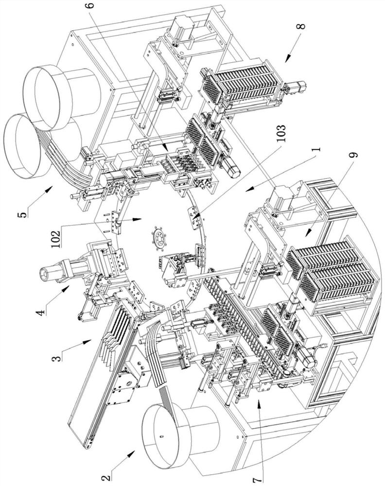
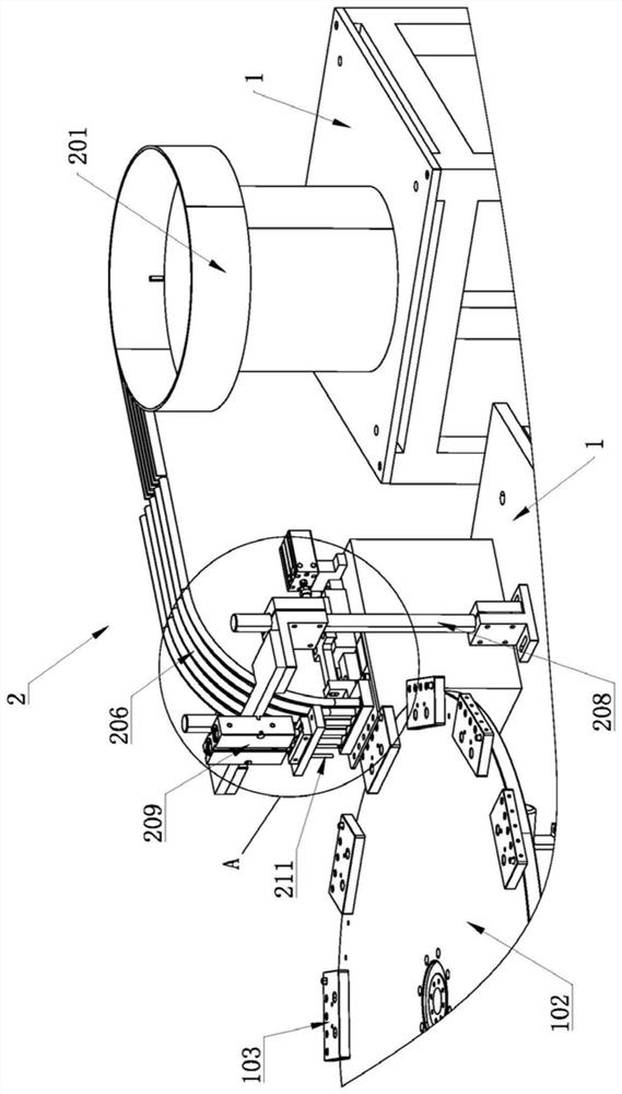
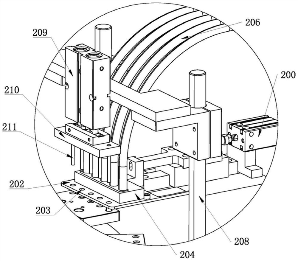
[0083] Such as figure 1 As shown, a sensor assembly machine includes a frame 1, and the frame 1 is provided with a turntable 102 driven by a drive device 101 (such as a combined power structure of a motor and a reducer), and the ring array on the turntable 102 has a plurality of Assembling seat 103 (for specific structure see Figure 5 ), each assembly seat is provided with a plurality of assembly holes 104, in this program, the assembly seat 103 protruding from the outer peripheral surface of the turntable 102 is provided with the assembly hole 104 position; The copper tube feeding device 2, the lens feeding device 3, the lens pressing device 4, the spring feeding device 5, the laser feeding device 6, and the finished product unloading device 7 are arranged in a ring; There is a laser feeding device 8, and the frame 1 at the end of the finished product unloading device 7 is p...


PUM


Abstract

The invention discloses a sensor assembling machine which comprises a rack, a rotating disc driven by a driving device is arranged on the rack, a plurality of assembling bases are annularly arranged on the rotating disc, and each assembling base is provided with an assembling hole. A copper pipe feeding device, a lens feeding device, a lens press-fitting device, a spring feeding device, a laser feeding device and a finished product discharging device are sequentially and annularly arranged on the portion, located on the periphery of the rotary disc, of the rack. A laser feeding device is arranged on one side of the laser feeding device, and a material box collecting device is arranged on the portion, located at the tail end of the finished product discharging device, of the rack. Mechanical automatic assembly of the sensor is achieved, the working continuity is high, the working efficiency of sensor assembly is greatly improved, and the assembly precision is high; meanwhile, the labor intensity of workers is effectively reduced, and in addition, the sensor assembling machine is reasonable and compact in structural arrangement and small in occupied space.

Description

technical field [0001] The invention belongs to the technical field of sensor assembly, in particular to a sensor assembly machine. Background technique [0002] An optical sensor includes a copper tube, in which there are lenses, springs, lasers and other devices in sequence. During assembly, it is necessary to manually install lenses, springs, lasers and other components into the copper tube in sequence. The assembled lasers are put into the box one by one for centralized collection. Using this method, the labor intensity of the staff is high, the work efficiency is low, and the assembly accuracy is low. Contents of the invention [0003] The invention provides a sensor assembly machine to realize mechanized automatic assembly, reduce labor intensity, improve work efficiency and assembly accuracy. [0004] In order to solve the above technical problems, the technical solution of the present invention is: a sensor assembly machine, including a frame, the frame is provide...

Claims


Application Information

Patent Timeline
Patent Type & Authority Applications(China)
IPC IPC(8): B23P21/00
CPCB23P21/006
Inventor 易均萍刘晓东戴文军沈一博熊磊
Owner 哈工大机器人南昌智能制造研究院
Learn More