Multi-die punching machine

A multi-mold and mold technology, which is applied in the field of punching machines, can solve the problems of high workshop area requirements, reduced processing efficiency, and large area occupied by punching machines, so as to achieve the effects of ensuring accuracy, avoiding deflection, and conveniently selecting specifications

Pending Publication Date: 2022-03-11
济南纽兰数控机械有限公司
View PDF0 Cites 0 Cited by
  • Summary
  • Abstract
  • Description
  • Claims
  • Application Information

AI Technical Summary

Problems solved by technology

However, the traditional punching machine can only complete the stamping of a single mold. If there are stamping structures of various specifications on the sheet, it is necessary to manually replace the punch, and its processing efficiency is greatly reduced.
[0003] There are also multi-mold punches now, but the punches of the current multi-mold punches are all immovable. The molds are set on the rotating disc structure, and the purpose of mold switching is achieved by driving the disc structure to rotate, but the disc structure requires The occupied area is larger, which also causes the punch itself to occupy a larger area, and the requirements for the factory area are also higher.

Method used


Image

  • Multi-die punching machine
  • Multi-die punching machine
  • Multi-die punching machine

Examples


Embodiment Construction

[0037]The present invention will be further described below in conjunction with accompanying drawing and specific embodiment, so that those skilled in the art can better understand the present invention and can be implemented, but the embodiment given is not as the limitation of the present invention, in the case of no conflict Next, the embodiments of the present invention and the technical features in the embodiments can be combined with each other.

[0038] It should be understood that in the description of the embodiments of the present invention, words such as "first" and "second" are only used to distinguish the purpose of description, and cannot be understood as indicating or implying relative importance, nor can they be understood as indicating or imply order. "Multiple" in the embodiments of the present invention refers to two or more.

[0039] The term "and / or" in the embodiment of the present invention is only an association relationship describing associated objec...


PUM


Abstract

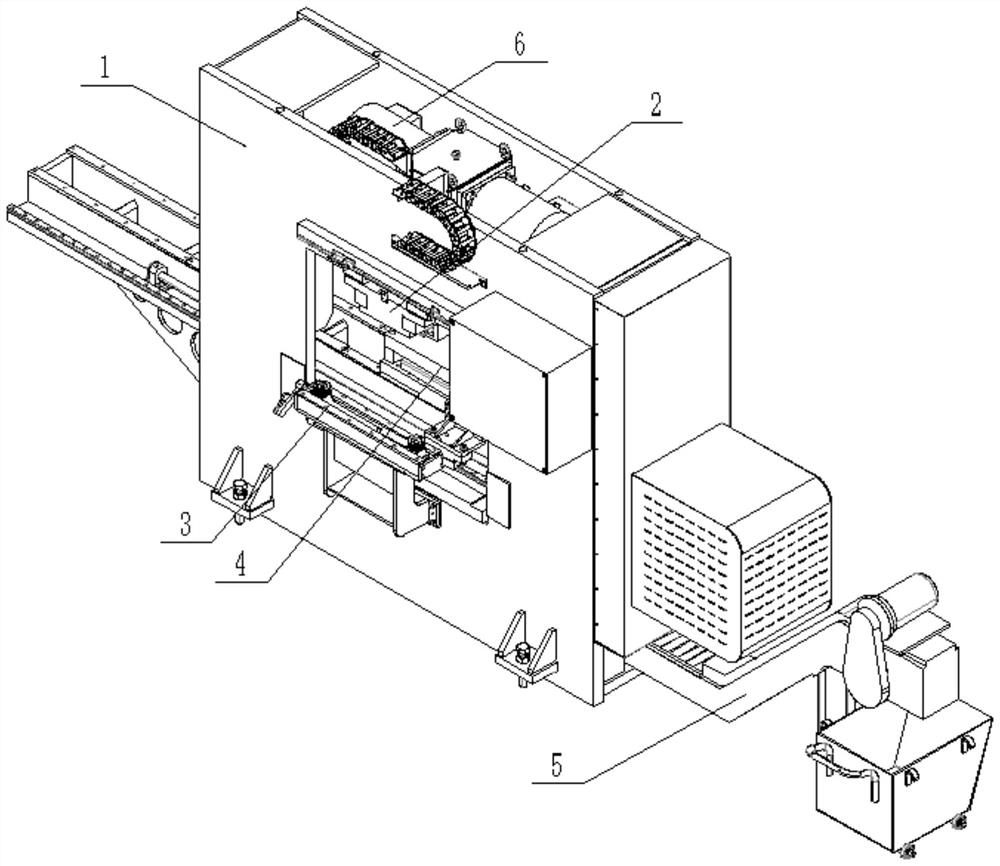
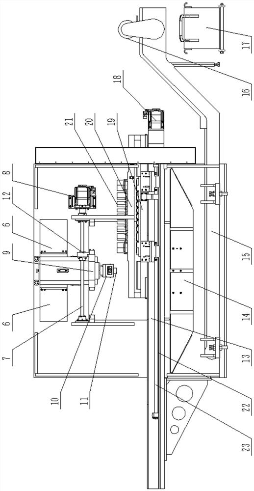
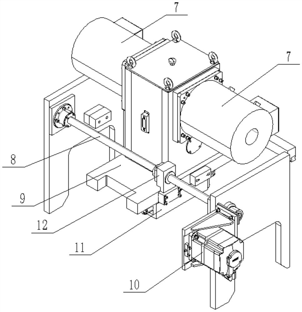
The multi-die punching machine comprises a machine body, a punching power device and a die switching device, the punching power device and the die switching device are arranged on the machine body, and the die switching device comprises a movable base, a plurality of dies arranged on the movable base and a first driving assembly used for driving the movable base to move in the length direction of the machine body. The stamping power device comprises a sliding plate, a second driving assembly used for driving the sliding plate to slide in the length direction of the lathe bed, a power stamping assembly fixedly arranged on the sliding plate and a transition assembly fixedly connected to an output element of the power stamping assembly. The transition assembly comprises a stamping head and a third driving assembly used for driving the stamping head to move in the width direction of the lathe bed, and when a plate needs to be stamped, a needed die is driven to the to-be-machined position of the plate through the first driving assembly; the punching head is driven to the position over the needed die through the second driving assembly and the third driving assembly.

Description

technical field [0001] The invention relates to the technical field of punching machines, in particular to a multi-die punching machine. Background technique [0002] Punching machine is one of the most common processing equipment in mechanical processing. The processing components of punching machine are mainly for sheet metal, with blanking, punching, forming, stretching, trimming, fine blanking, shaping and extrusion parts, etc., and are widely used in various fields. . The working principle of the punch press is to convert the circular motion of the motor into a linear motion through the crankshaft and connecting rod to apply pressure to the sheet material to make it plastically deformed. However, the traditional punch press can only complete the stamping of a single mold. If there are stamping structures of various specifications on the sheet, it is necessary to manually replace the punch, and its processing efficiency is greatly reduced. [0003] There are also multi...

Claims


Application Information

Patent Timeline
Patent Type & Authority Applications(China)
IPC IPC(8): B21D37/04B21D37/10B21D43/00B21D43/09B21D43/20
CPCB21D37/04B21D37/10B21D43/20B21D43/09B21D43/003
Inventor 李佳冯荣军
Owner 济南纽兰数控机械有限公司
Why Eureka
Try Eureka