


Quick Research
Generate reliable direction feasibility study reports for your R&D in just a few steps.

Technical Q&A
Discover and master advanced knowledge NOW. Basics, ideas, possibilities, all at once.

Find Solutions
As an expert in R&D theories, this can generate solutions to your technical problems instantly.

Evaluate Feasibility
Analyze your overall solution with one click, know your potential R&D risks in advance.

Monitor Landscape
Get weekly tech updates, stay abreast of the latest tech innovations and key insights.
Light leakage detection device and method for camera testing, assembling and bonding
A light leakage detection and camera module technology, which is applied in image communication, TV, color TV parts, etc., can solve the problem of lack of space between the lens group and the circuit board, the weak bonding between the lens group and the circuit board, and the impact on the image quality of the camera And other issues
- Summary
- Abstract
- Description
- Claims
- Application Information
AI Technical Summary
Problems solved by technology
Method used
Image

Examples
Embodiment 1
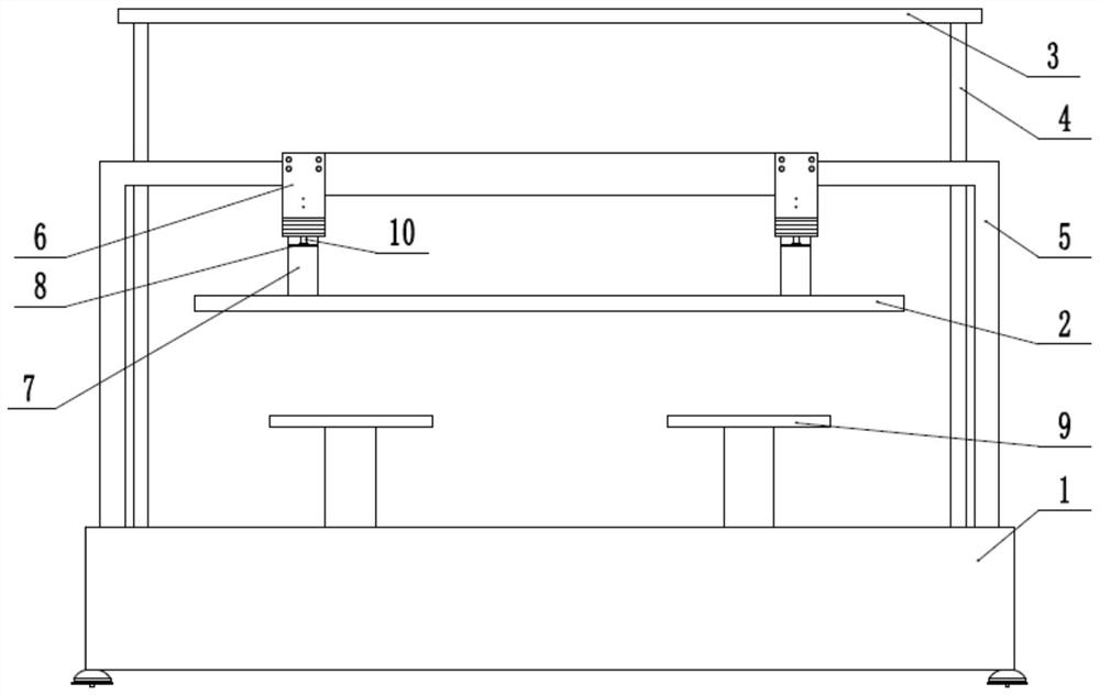
[0037] Light leakage detection device for camera test assembly bonding, such as figure 1 , figure 2 and image 3 Shown: It includes assembly and lamination machine 1 for assembling and laminating the lens group and circuit board to form a camera module. The lamination of the lens group and circuit board is carried out using existing UV glue, and the assembly and lamination machine 1 The bonded device can be assembled with the active calibration test of the existing ASM IS600GS model.
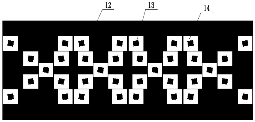
[0038] like image 3 As shown, the test chart card 12 with a plurality of marking points 13 is fixedly installed on the assembling and laminating machine 1. The marking point 13 is a black square with a side length of 0.5 cm. The test chart card 12 is located between the lens group and the circuit board. Above the loading platform 9, the outside of the preset range 14 of the marking point 13 is set as a light-blocking area, and the light-blocking area is filled with black, and the preset ran...
Embodiment 2
[0045] like Figure 4 As shown, this embodiment provides a light leakage detection method for camera test assembly and bonding, which can be applied to the light leakage detection device for camera test assembly and bonding in Embodiment 1, including the following:
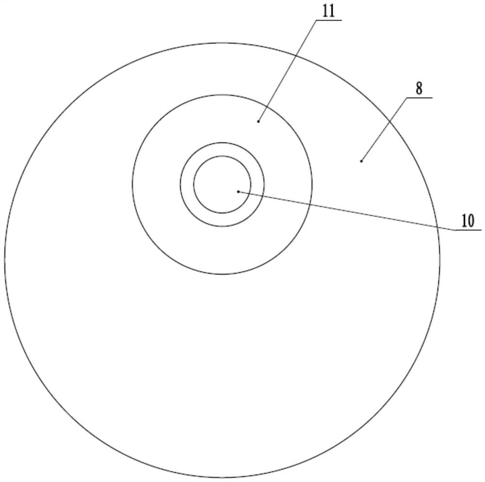
[0046] Set the area outside the preset range 14 of multiple mark points 13 on the test chart 12 as a light-blocking area, and the light-blocking area is filled with a black substance, and the test chart 12 is arranged above the lens group, for example, the test chart The card 12 is pasted on the transparent plate 2 in the first embodiment with a transparent tape, and the screw head 11 is rotated first, so that the side of the chuck 8 that is far from the center of the screw head 11 is away from the length scale, and stretched according to the camera module. Ruler 7 adjusts the height of the test chart card 12 from the lens group, that is, the test chart card 12 is set at the first preset distance above the lens gr...
PUM
 Abstract
Description
Claims
Application Information
 - R&D Engineer
- R&D Manager
- IP Professional
- Industry Leading Data Capabilities
- Powerful AI technology
- Patent DNA Extraction
Browse by: Latest US Patents, China's latest patents, Technical Efficacy Thesaurus, Application Domain, Technology Topic, Popular Technical Reports.
© 2024 PatSnap. All rights reserved.Legal|Privacy policy|Modern Slavery Act Transparency Statement|Sitemap|About US| Contact US: help@patsnap.com