
Intelligent reactive compensation module control circuit and control method thereof

A control circuit and compensation module technology, applied in reactive power compensation, reactive power adjustment/elimination/compensation, circuit devices, etc., can solve problems such as damage to capacitor banks, misjudgment of the zero point of the control module, large switching inrush current, etc., to achieve The effect of improving reliability

Pending Publication Date: 2022-03-08
JIANGSU MODERN POWER CAPACITOR
View PDF0 Cites 0 Cited by
  • Summary
  • Abstract
  • Description
  • Claims
  • Application Information

AI Technical Summary

Problems solved by technology

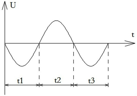
However, in the case of harmonics or interference during capacitor switching, the control module will misjudge the zero point, resulting in switching at a false zero point, resulting in a large switching inrush current, resulting in damage to the capacitor bank, etc.

Method used


Image

  • Intelligent reactive compensation module control circuit and control method thereof
  • Intelligent reactive compensation module control circuit and control method thereof
  • Intelligent reactive compensation module control circuit and control method thereof

Examples


Embodiment Construction

[0024] In order to explain in detail the technical solutions adopted by the present invention to achieve the intended technical purpose, the technical solutions in the embodiments of the present invention will be clearly and completely described below in conjunction with the drawings in the embodiments of the present invention. Obviously, the described implementation Examples are only part of the embodiments of the present invention, rather than all embodiments, and, on the premise of not paying creative work, the technical means or technical features in the embodiments of the present invention can be replaced, the following will refer to the accompanying drawings and combine Examples illustrate the present invention in detail.

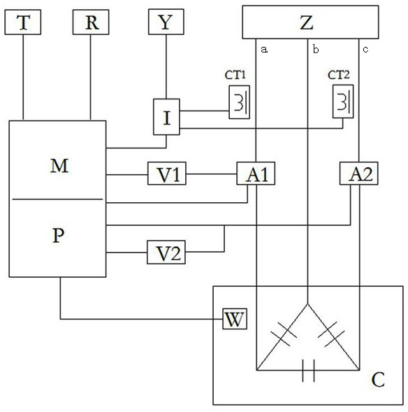
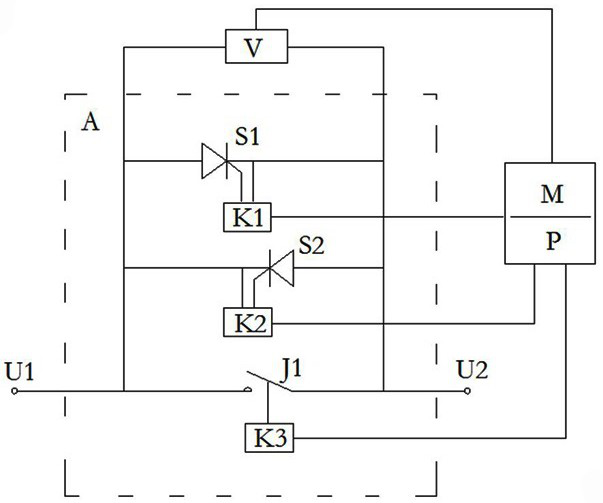
[0025] Such as figure 1 As shown, an intelligent reactive power compensation module control circuit of the present invention includes a low-voltage power capacitor body C, a main switch Z, a microprocessor circuit M, a switch circuit A1, a switch circ...


PUM


Abstract

The invention discloses an intelligent reactive compensation module control circuit, which comprises a low-voltage power capacitor body C, a main switch Z, a microprocessor circuit M, a switching circuit A1, a switching circuit A2, a voltage detection circuit V1, a voltage detection circuit V2, a current detection circuit I, a temperature acquisition circuit W, a communication circuit T, a power supply circuit P and a man-machine contact module R, the switching circuit A1, the switching circuit A2, the voltage detection circuit V1, the voltage detection circuit V2, the current detection circuit I, the temperature acquisition circuit W, the communication circuit T, the power supply circuit P and the man-machine contact module R are respectively connected with the microprocessor circuit M. According to the invention, the problems that the capacitor bank is easy to damage and the like due to inaccurate zero crossing point detection and large switching inrush current under the condition of harmonic waves or interference in the capacitor switching process of the conventional reactive compensation capacitor are solved, and the reliability of reactive compensation is improved.

Description

technical field [0001] The invention relates to a control circuit and a control method thereof, in particular to an intelligent reactive power compensation module control circuit and a control method thereof, belonging to the field of power capacitor equipment. Background technique [0002] Intelligent reactive power compensation capacitor is an intelligent reactive power compensation device integrating advanced technologies such as modern measurement and control, power electronics, network communication, automatic control, and power capacitors. Intelligent reactive power compensation capacitors have changed the backward control technology of traditional reactive power compensation devices and the backward switching technology of mechanical contactors or mechatronic switches as switching capacitors, and changed the bulky and cumbersome structure of traditional reactive power compensation devices Mode, so that the new generation of low-voltage reactive power compensation equi...

Claims


Application Information

Patent Timeline
Patent Type & Authority Applications(China)
IPC IPC(8): H02J3/18H02J13/00H02H7/26
CPCH02J3/18H02J3/1821H02J13/00001H02J13/00006H02J13/00016H02H7/262Y02E40/30Y02B90/20Y04S40/12Y04S40/124
Inventor 沈卫峰冯国伟张锐孟领刚沈周斌王宗臣夏文夏武邱素素李天鹰薛玲丽陈佳佳柳振铁杨建
Owner JIANGSU MODERN POWER CAPACITOR
Learn More