


Quick Research
Generate reliable direction feasibility study reports for your R&D in just a few steps.

Technical Q&A
Discover and master advanced knowledge NOW. Basics, ideas, possibilities, all at once.

Find Solutions
As an expert in R&D theories, this can generate solutions to your technical problems instantly.

Evaluate Feasibility
Analyze your overall solution with one click, know your potential R&D risks in advance.

Monitor Landscape
Get weekly tech updates, stay abreast of the latest tech innovations and key insights.
Decorative structure of vertical support
A decorative structure and vertical technology, applied in decorations, building structures, other household appliances, etc., can solve the problems of low degree of automation and difficult processing, achieve automatic production, reduce the difficulty of production and processing, and improve connection strength. and tear resistance
- Summary
- Abstract
- Description
- Claims
- Application Information
AI Technical Summary
Problems solved by technology
Method used
Image

Examples
Embodiment 1
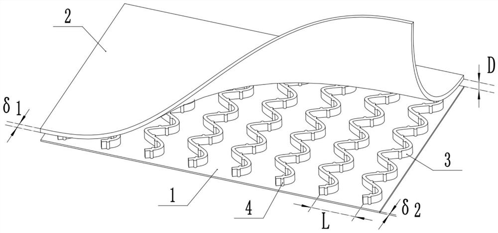
[0038] Embodiment one is basically as attached figure 1 Shown: a vertically supported decorative structure, including a horizontally arranged base plate 1 and a panel 2 located above the base plate 1 and parallel to the base plate 1 , connected between the base plate 1 and the panel 2 The support member, in this embodiment, the support member includes vertically arranged support plates 3 , the number of support plates 3 is multiple, and the plurality of support plates 3 are arrayed between the bottom plate 1 and the panel 2 along the horizontal direction.
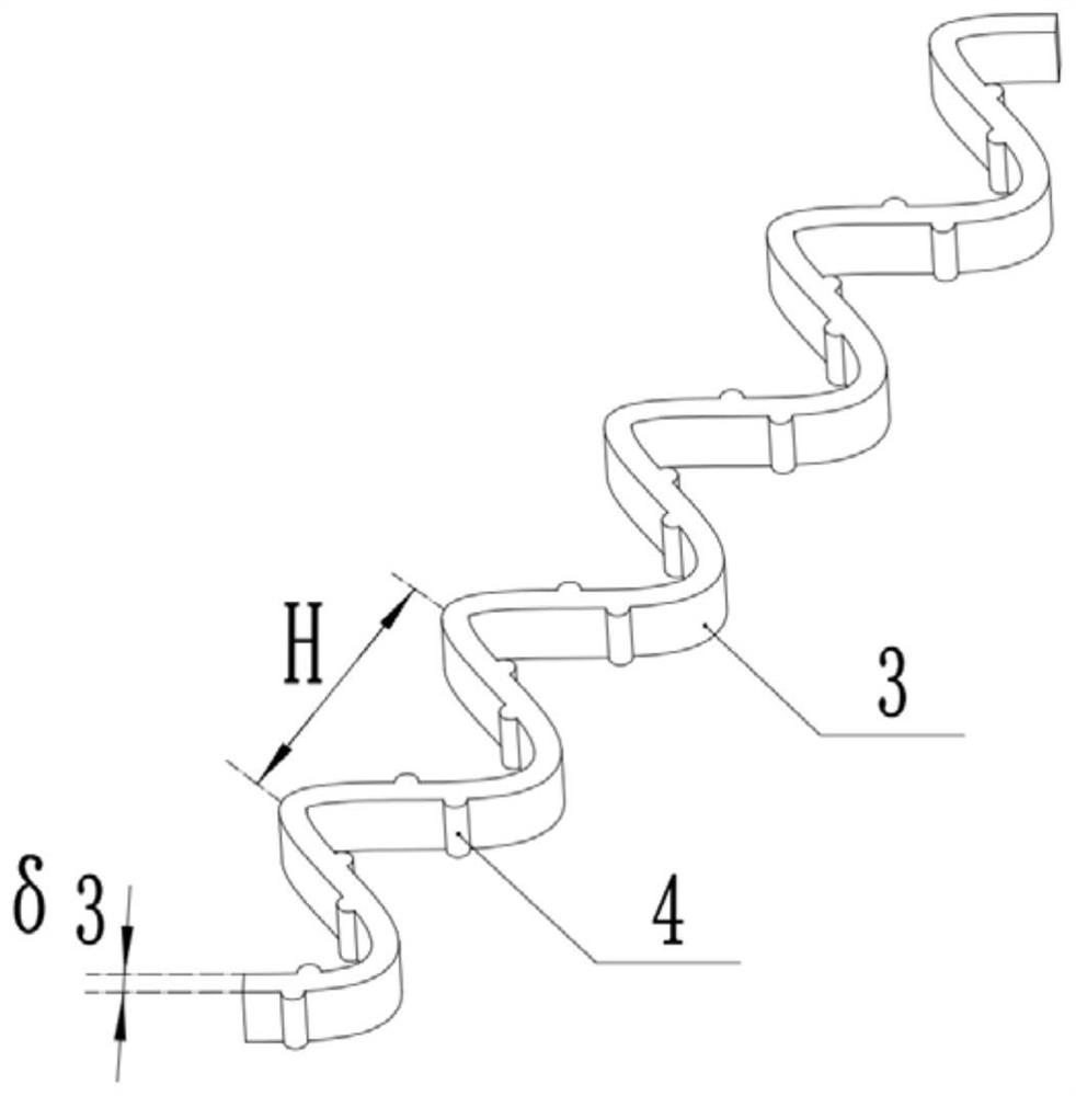
[0039] combine figure 1 with figure 2 , the support plate 3 has a reciprocating bending structure, and the cross section of the reciprocating bending structure is one or more combinations of tooth shape, wave shape, W shape or U shape, figure 2 shows the schematic structure of the support plate 3 in a wavy shape. In this embodiment, the reciprocating bending structure on the same support plate 3 is the same, but in othe...
Embodiment 2
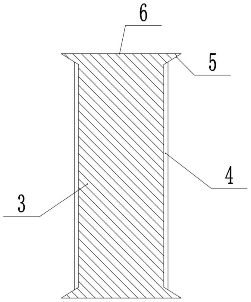
[0044] The difference between embodiment two and embodiment one is: as image 3 As shown, in this embodiment, both ends of the support plate 3 are fixedly connected with a reinforcement portion, and the reinforcement portion is provided with a contact surface 6 facing the bottom plate 1 or the panel 2. In this embodiment, the reinforcement portion includes an integrally formed The rolling end 5 at the top and bottom of the support plate 3 and the contact surface 6 are arranged on the top and bottom of the rolling end 5, so that the longitudinal section of the support plate 3 is I-shaped.
[0045] In this embodiment, by setting the rolling end 5 and the contact surface 6 on the rolling end 5, the support plate 3 has an I-shaped steel structure as a whole, so that the support plate 3 has better stability than the vertical plate state. property, and when the support plate 3 is combined with the bottom plate 1 and the panel 2, since the contact surface 6 is in surface contact with...
Embodiment 3
[0047] The difference between embodiment three and embodiment two is: as Figure 4 As shown, a receiving portion is provided on the contact surface 6. In this embodiment, the receiving portion includes a receiving groove 7 opened on the contact surface 6. The receiving groove 7 is arranged along the length direction of the support plate 3, and the two sides of the receiving groove 7 The end does not pass through the two ends of the support plate 3, so that the accommodation groove 7 has a good effect of accommodation and anti-loss. Specifically, the accommodation groove 7 can be integrally formed at the same time when the rolling end 5 is integrally formed. In other embodiments other than this embodiment, the number of receiving grooves 7 may be multiple, and the receiving parts may also be arranged in a grid structure or other shapes, which will not be repeated here. In this embodiment, by setting the accommodation part, when the support plate 3 is composited between the bott...
PUM
 Abstract
Description
Claims
Application Information
 - R&D Engineer
- R&D Manager
- IP Professional
- Industry Leading Data Capabilities
- Powerful AI technology
- Patent DNA Extraction
Browse by: Latest US Patents, China's latest patents, Technical Efficacy Thesaurus, Application Domain, Technology Topic, Popular Technical Reports.
© 2024 PatSnap. All rights reserved.Legal|Privacy policy|Modern Slavery Act Transparency Statement|Sitemap|About US| Contact US: help@patsnap.com