
Multi-station injection molding mold

An injection molding, multi-station technology, applied in the field of molds, can solve problems such as easy-to-bond residual materials, white spots, and affect production efficiency, and achieve the effects of increasing the force-bearing area of ​​ejection, reducing the number of uses, and increasing production efficiency.

Pending Publication Date: 2022-03-08
湖南登科材料科技有限公司
View PDF0 Cites 0 Cited by
  • Summary
  • Abstract
  • Description
  • Claims
  • Application Information

AI Technical Summary

Problems solved by technology

[0003] However, there are still certain defects in existing injection molding molds, especially when plastics such as PC or PVC need to be injected, because PC and PVC plastics are easily bonded to the cavity of the mold, the thimble in the ejection mechanism needs to be installed during demoulding. Multiple groups, because the force surface is small, it is easy to cause white spots on the lower molding surface of the molded plastic during ejection, which affects product quality, and the gap between the ejector pin and the lower mold is easy to bond residual materials, which affects the movement and movement of the ejector pin. The quality of the molding surface under the molded plastic often requires manual cleaning, which affects production efficiency

Method used


Image

  • Multi-station injection molding mold
  • Multi-station injection molding mold
  • Multi-station injection molding mold

Examples


Embodiment Construction

[0025] In order to make the technical means, creative features, goals and effects achieved by the present invention easy to understand, the present invention will be further described below in conjunction with specific embodiments.

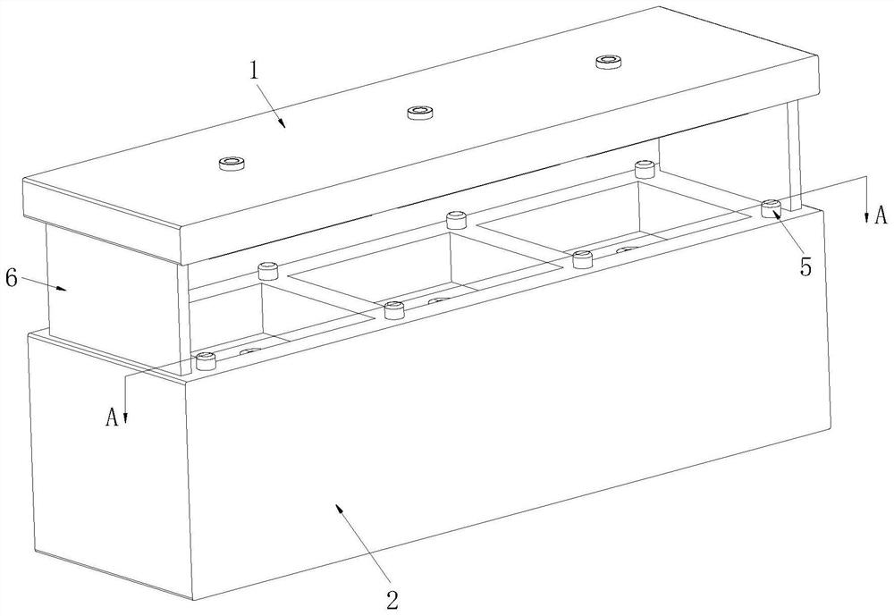
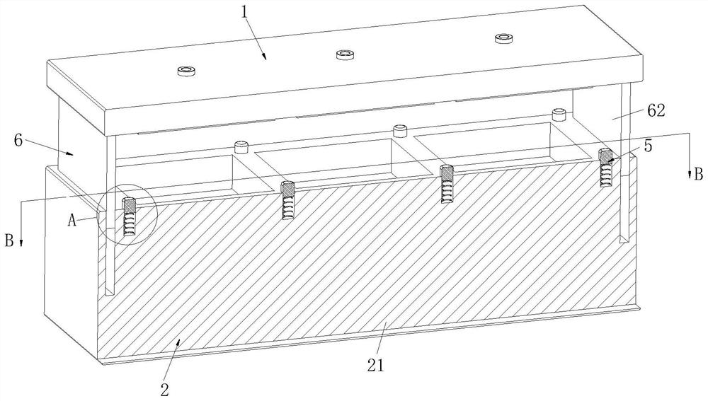
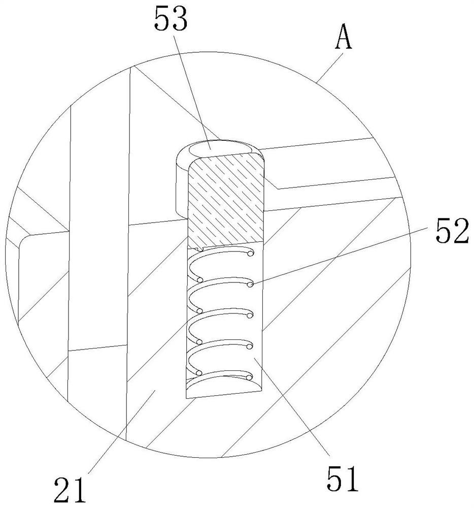
[0026] Such as Figure 1-Figure 9 As shown, a multi-station injection molding mold according to the present invention includes an upper mold clamping unit 1 and a lower mold clamping unit 2, the upper mold clamping unit 1 is located directly above the lower mold clamping unit 2, and the upper mold clamping unit 1 Cooperating with the lower mold clamping unit 2, the lower mold clamping unit 2 is provided with a plurality of ejector mechanisms 3, and the ejector rod mechanism 3 is provided with four circularly distributed cleaning mechanisms 4, and the lower mold clamping unit 2 is provided with a buffer Mechanism 5, an auxiliary mechanism 6 is provided between the upper mold clamping unit 1 and the lower mold clamping unit 2, through mutual mold cl...


PUM


Abstract

The invention relates to the field of molds, in particular to a multi-station injection molding mold which comprises an upper mold closing unit and a lower mold closing unit, the upper mold closing unit is located over the lower mold closing unit, the upper mold closing unit and the lower mold closing unit are matched, a plurality of ejector rod mechanisms are arranged in the lower mold closing unit, and the ejector rod mechanisms are matched with the upper mold closing unit and the lower mold closing unit. An ejector rod mechanism is arranged on the upper mold closing unit, four cleaning mechanisms which are annularly distributed are arranged in the ejector rod mechanism, a buffer mechanism is arranged on the lower mold closing unit, and an auxiliary mechanism is arranged between the upper mold closing unit and the lower mold closing unit. A stress surface is small, white points are easily formed on a molded plastic lower molding surface during ejection, the product quality is influenced, a gap of a flush plane of an ejector pin and a lower mold is easily adhered with defective materials, the movement of the ejector pin and the quality of the molded plastic lower molding surface are influenced, manual cleaning is often needed, and the production efficiency is influenced.

Description

technical field [0001] The invention relates to the field of molds, in particular to a multi-station injection molding mold. Background technique [0002] The plastic is first heated and melted in the heating barrel of the injection molding machine, and then driven by the screw or piston of the injection molding machine, it enters the mold cavity through the nozzle and the gating system of the mold, and finally hardens and shapes in the cavity. This is the simple process of injection molding. , and the mold used for injection molding is called an injection molding mold. The injection molding mold is divided into an upper mold, a lower mold and an ejection mechanism. The ejector pin ejects the injected plastic. [0003] However, there are still certain defects in existing injection molding molds, especially when plastics such as PC or PVC need to be injected, because PC and PVC plastics are easily bonded to the cavity of the mold, the thimble in the ejection mechanism needs ...

Claims


Application Information

Patent Timeline
Patent Type & Authority Applications(China)
IPC IPC(8): B29C45/17B29C45/26B29C45/40
CPCB29C45/4005B29C45/1753B29C45/2602B29C2045/4063
Inventor 李鹏建邓志勇熊世杰
Owner 湖南登科材料科技有限公司
Learn More