Switching power supply circuit
A switching power supply circuit and switching technology, which is applied in the direction of high-efficiency power electronic conversion, electrical components, and adjusting electric variables, etc., can solve the problems of switching power supply with wide input and output voltage range and high system efficiency, and achieve wide input and output voltage range , high efficiency effect
- Summary
- Abstract
- Description
- Claims
- Application Information
AI Technical Summary
Problems solved by technology
Method used
Image
Examples
Embodiment 1
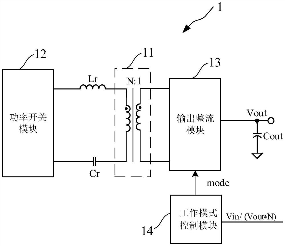
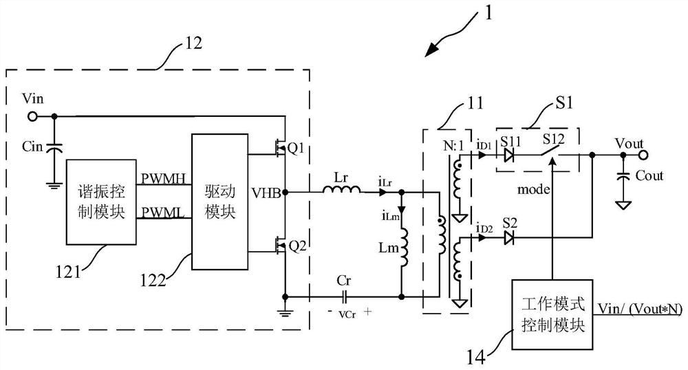
[0086] Such as figure 2 As shown, this embodiment provides a switching power supply circuit 1, and the switching power supply circuit 1 includes:
[0087] Transformer 11 , resonant capacitor Cr, resonant inductance Lr, power switch module 12 , output rectifier module 13 and working mode control module 14 .
[0088] Such as figure 2 As shown, as an example, the power switch module 12 is a half-bridge structure, including a first power switch tube Q1 and a second power switch tube Q2 connected in series between the input voltage Vin and the reference ground, the first power switch The first terminal of the switching tube Q1 receives the input voltage Vin, the second terminal is connected to the first terminal of the second power switching tube Q2; the second terminal of the second power switching tube Q2 is grounded. The second end of the first power switch tube Q1 and the first end of the second power switch tube Q2 are grounded sequentially via the resonant inductor Lr, th...
Embodiment 2
[0099] Such as Figure 9 As shown, the present embodiment provides a switching power supply circuit 1 , which is different from the first embodiment in that the structure of the output rectification module 13 is different.
[0100] Such as Figure 9 As shown, the secondary winding includes a third secondary winding and a fourth secondary winding. The output rectifying module 13 includes a third switch unit S3 , a fourth switch unit S4 , a fifth switch unit S5 , a first capacitor C1 and a second capacitor C2 . The current input end of the third switch unit S3 is connected to the same-named end of the third secondary winding and the primary winding, and the current output end is connected to the output capacitor Cout and the upper plate of the first capacitor C1; In the AHB mode, the third switch unit S3 is turned on and rectifies the signal input to the third switch unit S3, and in the AHB mode, the third switch unit S3 is turned off. The lower plate of the first capacitor C...
Embodiment 3
[0107] Such as Figure 12 As shown, this embodiment provides a switching power supply circuit 1. The difference from Embodiments 1 and 2 is that the structure of the output rectification module 13 is different. In this embodiment, the output rectification module 13 adopts a full-bridge rectifier structure.
[0108] Such as Figure 12 As shown, the secondary winding includes a fifth secondary winding. The output rectifying module 13 includes a sixth switch unit S6 , a seventh switch unit S7 , an eighth switch unit S8 and a ninth switch unit S9 . The current input terminal of the sixth switch unit S6 is connected to the same-named terminal of the fifth secondary winding and the primary winding, and the current output terminal is connected to the upper plate of the output capacitor Cout; both in LLC mode and AHB mode. The signal input to the sixth switch unit S6 is rectified. The current input terminal of the seventh switch unit S7 is grounded, and the current output terminal...
PUM
 Abstract
Description
Claims
Application Information
 - R&D Engineer
- R&D Manager
- IP Professional
- Industry Leading Data Capabilities
- Powerful AI technology
- Patent DNA Extraction
Browse by: Latest US Patents, China's latest patents, Technical Efficacy Thesaurus, Application Domain, Technology Topic, Popular Technical Reports.
© 2024 PatSnap. All rights reserved.Legal|Privacy policy|Modern Slavery Act Transparency Statement|Sitemap|About US| Contact US: help@patsnap.com


