
Monitoring equipment for vibration deformation at joint of highway bridge

A technology for highway bridges and monitoring equipment, which is applied in vibration testing, mechanical solid deformation measurement, and testing of machine/structural components. It can solve problems such as poor practicability and inconvenient support, and achieve the effect of diversification of functions and improvement of practicability

Pending Publication Date: 2022-03-04
林海军
View PDF1 Cites 0 Cited by
  • Summary
  • Abstract
  • Description
  • Claims
  • Application Information

AI Technical Summary

Problems solved by technology

[0005] But this device also has the disadvantage that the device is supported by the support seat when the device is used, and when the bridge is detected, because the bridge is high, the support is relatively inconvenient, resulting in poor practicability of the device , at the same time, because the device is not convenient to actually express the degree of deformation and dislocation generated by the joint under vibration, the practicability of the device is poor. In view of this, we propose a monitoring device for vibration deformation of the road bridge joint

Method used


Image

  • Monitoring equipment for vibration deformation at joint of highway bridge
  • Monitoring equipment for vibration deformation at joint of highway bridge
  • Monitoring equipment for vibration deformation at joint of highway bridge

Examples


Embodiment Construction

[0033] Please refer to Fig. 1-7, the present invention provides a kind of technical scheme:

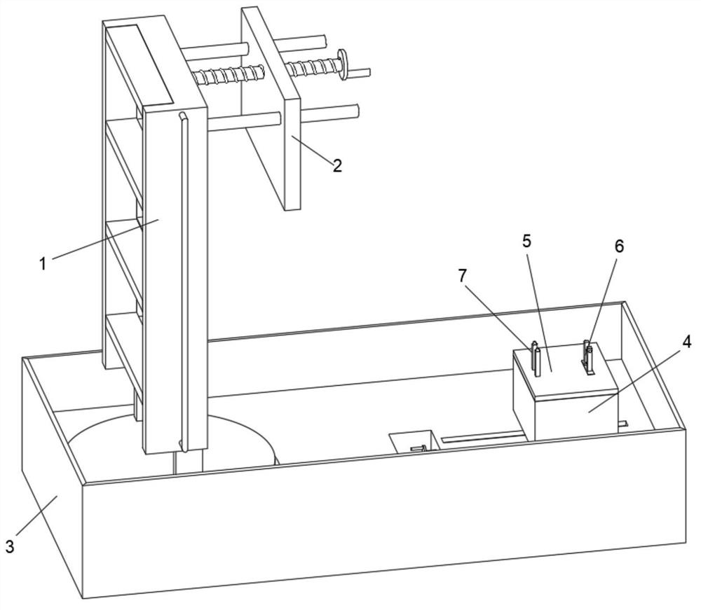
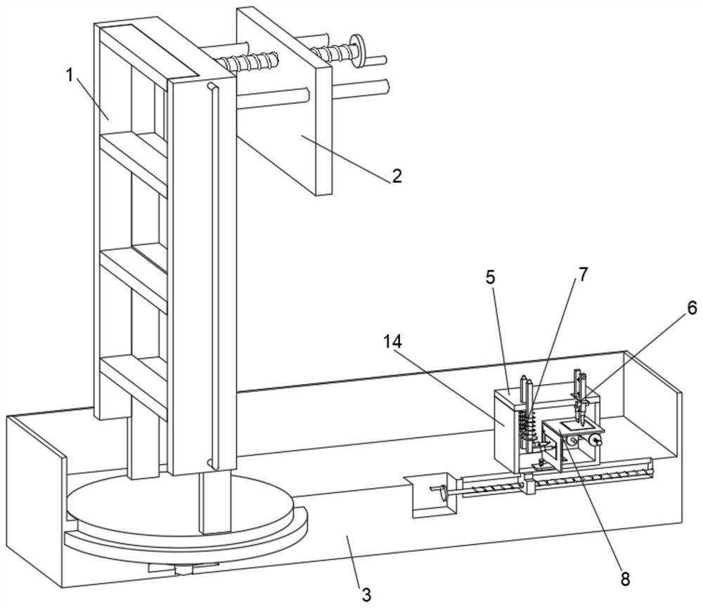
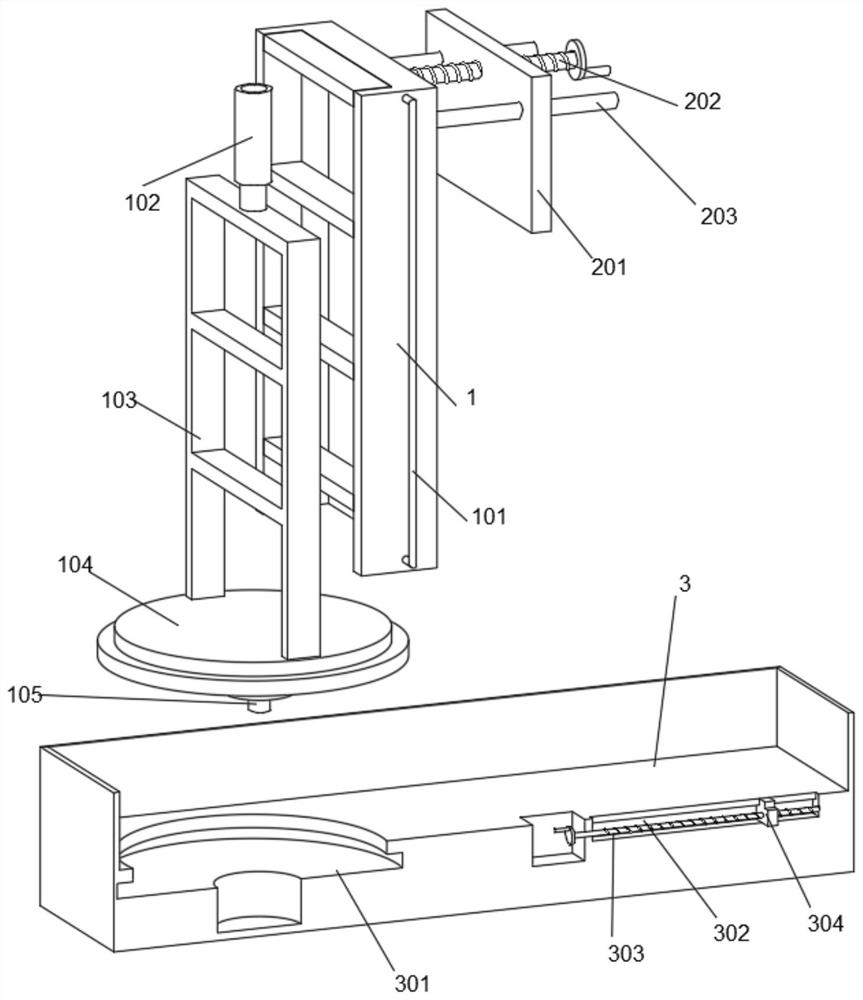
[0034] The monitoring equipment for vibration deformation at the joints of highway bridges includes a fixed ladder 1, a fixed component 2 is arranged on the upper right side of the fixed ladder 1, a base 3 is arranged on the lower side of the fixed ladder 1, and an equipment box 4 is arranged on the upper right side of the base 3;

[0035] The top surface of the equipment box 4 is provided with a box cover 5, the top surface of the right side of the box cover 5 is provided with a seam spacing monitoring component 6, the top surface of the other side of the box cover 5 is provided with a joint up and down dislocation monitoring component 7, and the equipment box 4 is equipped with There is a mounting frame 8, the upper and lower sides of the mounting frame 8 are provided with a distance surveying and mapping assembly 9, and the inner side of the left end of the mounting frame 8 is provi...


PUM


Abstract

The invention discloses monitoring equipment for vibration deformation at a joint of a highway bridge, and belongs to the related technical field of the highway bridge. The highway bridge joint vibration deformation monitoring equipment comprises a fixed ladder, a fixed assembly is arranged on the right side of the upper end of the fixed ladder, and an equipment box is arranged above the right side of a base; a box cover is arranged on the top face of the equipment box, a joint vertical dislocation monitoring assembly is arranged on the top face of the other side of the box cover, a mounting frame is arranged in the equipment box, a distance surveying and mapping assembly is arranged on the lower side of the upper end of the mounting frame, and a vertical dislocation surveying and mapping assembly is arranged on the inner side of the left end of the mounting frame. The device can be applied to monitoring of a high bridge joint, the practicability of the device is improved, the distance between two beam bodies at the bridge joint can be drawn in real time under the vibration condition by arranging the joint interval monitoring assembly and the interval surveying and mapping assembly, and comparative research on monitored data is facilitated.

Description

technical field [0001] The invention relates to the technical field related to highway bridges, and more specifically, to monitoring equipment for vibration deformation at joints of highway bridges. Background technique [0002] The role of bridge expansion joints is to adjust the displacement between the superstructures and the connection between the superstructures caused by the characteristics of the vehicle load environment and the physical properties of the bridge building materials. The bridge expansion joint device is a part of the bridge structure. If the design is improper, the installation quality is poor, and the maintenance is not timely, etc., it will cause jumping at the bridge expansion joint. [0003] The problem of vehicle jumping at the bridge head expansion joint is a relatively common road defect on domestic highways. With the development of my country's highways, this problem has become more and more prominent. The expansion joints of the bridge are dam...

Claims


Application Information

Patent Timeline
IPC IPC(8): G01M7/02G01B5/30G01B5/14
CPCG01M7/02G01M7/025G01B5/30G01B5/14
Inventor 林海军张江斌张晓敏申保有秦天梁瑾王小帅王怀晋梁瑜梁霞
Owner 林海军
Learn More