
Engine thermal management system and method

A thermal management system and engine technology, applied in the direction of engine control, engine components, combustion engine, etc., can solve the problem of high fuel consumption of the engine, achieve the effect of improving fuel economy, improving utilization efficiency, and reducing the amount of NOx generated

Pending Publication Date: 2022-03-04
SINO TRUK JINAN POWER
View PDF0 Cites 0 Cited by
  • Summary
  • Abstract
  • Description
  • Claims
  • Application Information

AI Technical Summary

Problems solved by technology

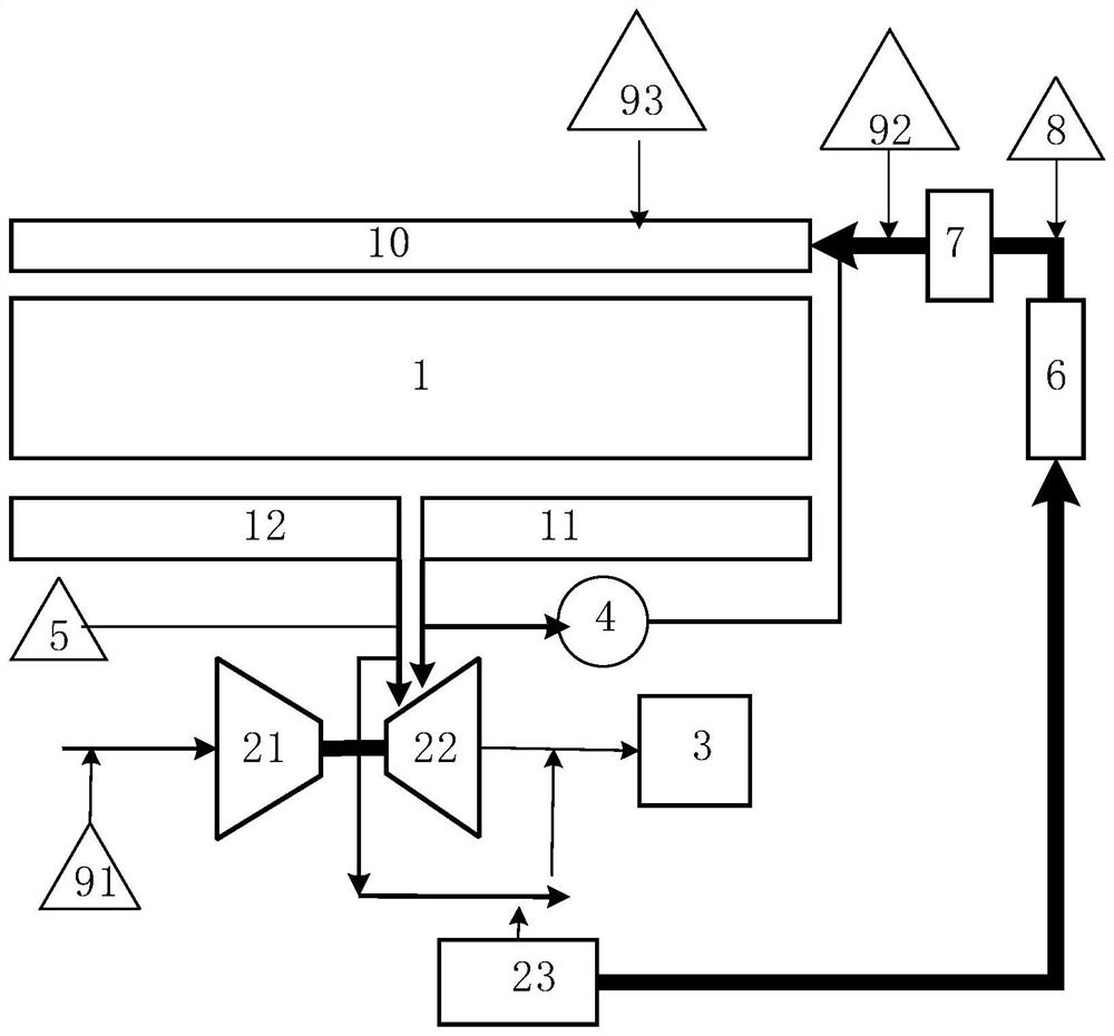
[0004] The invention provides an engine thermal management system and method, which are used to solve the problem of high engine fuel consumption caused by the existing supercharger pressure control

Method used


Image

  • Engine thermal management system and method
  • Engine thermal management system and method

Examples


Embodiment Construction

[0029] In order to clearly illustrate the technical features of this solution, the present invention will be described in detail below through specific implementation modes and in conjunction with the accompanying drawings. The following disclosure provides many different embodiments or examples for implementing different structures of the present invention. To simplify the disclosure of the present invention, components and arrangements of specific examples are described below. Furthermore, the present invention may repeat reference numerals and / or letters in different instances. This repetition is for the purpose of simplicity and clarity and does not in itself indicate a relationship between the various embodiments and / or arrangements discussed. It should be noted that components illustrated in the figures are not necessarily drawn to scale. Descriptions of well-known components and processing techniques and processes are omitted herein to avoid unnecessarily limiting the...


PUM


Abstract

The invention provides an engine thermal management system and method.The system comprises a thermal management valve and an electric control bypass valve, the thermal management valve is connected with a first exhaust manifold of an engine, and the electric control bypass valve is connected with a second exhaust manifold of the engine; the thermal management system further comprises an exhaust back pressure valve, and the exhaust back pressure valve is connected with the vortex end. Combustion waste gas of the engine is used for providing energy for the gas compressor through acting of a turbine of the turbocharger; and in combination with a fed-back turbine front pressure signal, closed-loop regulation of turbine efficiency is realized through combined regulation and control of a designed thermal management valve, an electric control bypass valve and an exhaust back pressure valve. Control and closed-loop adjustment of the efficiency of the turbocharger of the engine have great effects on improvement of the utilization efficiency of exhaust energy and improvement of fuel economy.

Description

technical field [0001] The invention relates to the technical field of engines, in particular to an engine thermal management system and method. Background technique [0002] The intake and exhaust system of a diesel engine is mainly composed of an exhaust manifold, a turbocharger and related pipelines. The main function is to use the energy of the exhaust gas burned by the engine to drive the compressor to pressurize the intake air and increase the intake air density. [0003] In order to improve the economy of the engine and reduce fuel consumption, the utilization efficiency of exhaust gas, that is, the efficiency of the supercharger is an important part. In addition to the influence of the efficiency of the supercharger itself, the control of the engine on the efficiency of the supercharger also affects the supercharger. important part of efficiency. At present, the control mode of the supercharger is gradually upgraded from a passively controlled bypass valve superchar...

Claims


Application Information

Patent Timeline
Patent Type & Authority Applications(China)
IPC IPC(8): F02B37/18F02M26/05F02D41/00F02D41/14
CPCF02B37/183F02M26/05F02D41/0007F02D41/0047F02D41/1439F02D41/1448F02D2200/04Y02T10/12
Inventor 刘怀强秦善斌侯乐福李聪
Owner SINO TRUK JINAN POWER
Learn More