Supercharge Your Innovation With Domain-Expert AI Agents!

Automatic feeding and conveying device for strip cutting machine

A technology of automatic feeding and conveying device, applied in the direction of conveyor control device, conveyor, conveyor objects, etc., can solve the problems of low efficiency and need personnel cost, and achieve the effect of improving work efficiency and saving personnel cost.

Pending Publication Date: 2022-03-04
万载县株潭镇兴业筒子厂
View PDF0 Cites 0 Cited by
  • Summary
  • Abstract
  • Description
  • Claims
  • Application Information

AI Technical Summary

Problems solved by technology

The short paper tube is a container for gunpowder. The existing short paper tube production method is that the cardboard is rolled into a long paper tube by a rubbing machine, and then cut into several short paper tubes by a strip cutter. The existing strip cutter needs Artificially transport the paper tube produced by the rubbing machine to the container wooden board on the strip cutting machine, and then push the wooden board to move, so that the knife belt can cut the long paper tube. This method is inefficient and requires personnel costs, which has shortcomings.

Method used


Image

  • Automatic feeding and conveying device for strip cutting machine
  • Automatic feeding and conveying device for strip cutting machine
  • Automatic feeding and conveying device for strip cutting machine

Examples


Embodiment Construction

[0040] The following will clearly and completely describe the technical solutions in the embodiments of the present invention with reference to the accompanying drawings in the embodiments of the present invention. Obviously, the described embodiments are only some, not all, embodiments of the present invention. Based on the embodiments of the present invention, all other embodiments obtained by persons of ordinary skill in the art without making creative efforts belong to the protection scope of the present invention.

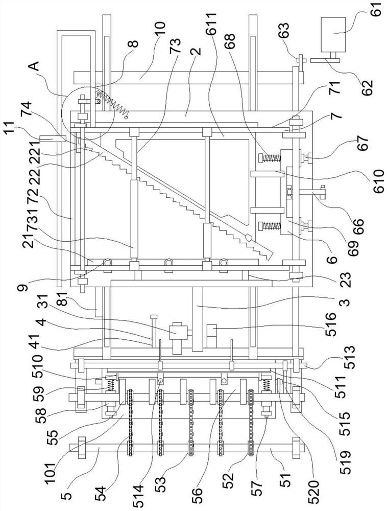
[0041] refer to Figure 1 to Figure 17 , an automatic feeding and conveying device for a strip cutting machine, comprising:

[0042] Rack 10;

[0043] The workbench 2 is provided with a straight stop rod 21 and an oblique stop rod 22, the straight stop rod 21 and the oblique stop rod 22 can move relative to the workbench 2, and several interconnected grooves 221;

[0044] The first driving device 3 is used to drive the workbench 2 to move back and forth on th...


PUM


Abstract

The invention discloses an automatic feeding and conveying device for a strip cutting machine. The automatic feeding and conveying device comprises a rack; a straight stop lever and an inclined stop lever are arranged on the workbench, and a plurality of grooves which are connected with one another are formed in one side of the inclined stop lever; the first driving device is used for driving the workbench to move back and forth on the rack; the second driving device is used for indirectly driving the straight stop lever to move back and forth on the workbench; the feeding device is used for receiving the long paper tubes produced by the strip twisting machine and orderly conveying the long paper tubes to the workbench; the third driving device is used for indirectly driving the inclined stop lever to move back and forth on the workbench; the pressing device is used for pressing the plurality of long paper tubes on the workbench; and the fourth driving device is used for driving the pressing device to act so that the pressing device can be attached to or separated from the long paper tube. According to the automatic feeding device, the strip twisting machine and the strip cutting machine can be connected together for use, the purpose of automatic feeding and conveying is achieved, manual feeding is not needed, the working efficiency is improved, and the labor cost is saved.

Description

technical field [0001] The invention relates to the technical field of material conveying, in particular to an automatic feeding conveying device for a strip cutter. Background technique [0002] Fireworks and firecrackers are made of pyrotechnic powder as the main raw material. After being ignited, they burn or explode to produce effects such as light, sound, color, shape, and smoke, and are used for viewing. Fireworks are products that can form colors, patterns, and produce sound effects when they are set off, and are mainly visual effects. Firecrackers are products whose main body explodes when set off and can produce popping sounds, flashes and other effects, mainly based on auditory effects. The short paper tube is a container for gunpowder. The existing short paper tube production method is that the cardboard is rolled into a long paper tube by a rubbing machine, and then cut into several short paper tubes by a strip cutter. The existing strip cutter needs Artificial...

Claims


Application Information

Patent Timeline
IPC IPC(8): B26D7/06B26D7/08B26D7/02B65G17/30B65G17/40B65G43/08B65G47/74B65G47/82
CPCB26D7/0608B26D7/0625B26D7/02B26D7/08B65G17/40B65G17/30B65G43/08B65G47/82B65G47/74B26D2007/0012
Inventor 田冬生陈和清
Owner 万载县株潭镇兴业筒子厂
Features
  • R&D
  • Intellectual Property
  • Life Sciences
  • Materials
  • Tech Scout
  • Unparalleled Data Quality
  • Higher Quality Content
  • 60% Fewer Hallucinations
Learn More