Bean sprout auxiliary planting device

A planting device and technology of bean sprouts, applied in botany equipment and methods, soilless cultivation, cultivation, etc., can solve problems such as automatic planting of difficult bean sprouts and rational management of difficult bean sprouts

Pending Publication Date: 2022-03-04
林寿伟
View PDF5 Cites 0 Cited by
  • Summary
  • Abstract
  • Description
  • Claims
  • Application Information

AI Technical Summary

Problems solved by technology

[0004] In order to overcome the shortcomings of the existing bean sprouts planting that it is difficult to rationalize the management of bean sprouts and the automatic planting of bean sprouts, the technical problem of the present invention is to provide a bean sprouts auxiliary planting device that can realize automatic planting and reasonable management of bean sprouts

Method used


Image

  • Bean sprout auxiliary planting device
  • Bean sprout auxiliary planting device
  • Bean sprout auxiliary planting device

Examples


Embodiment 1

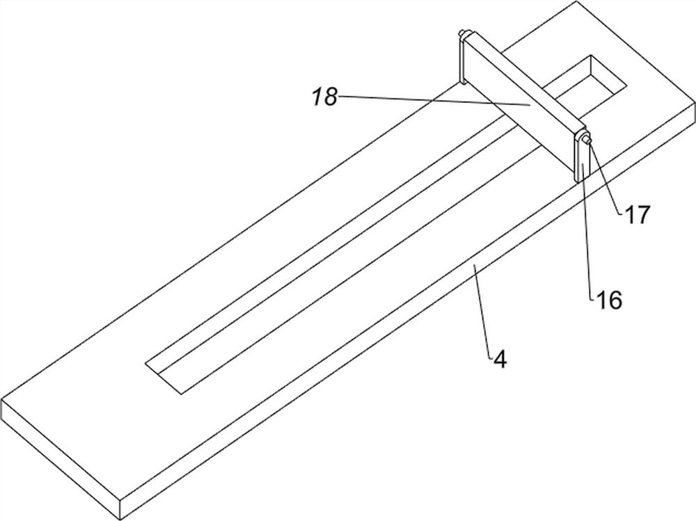
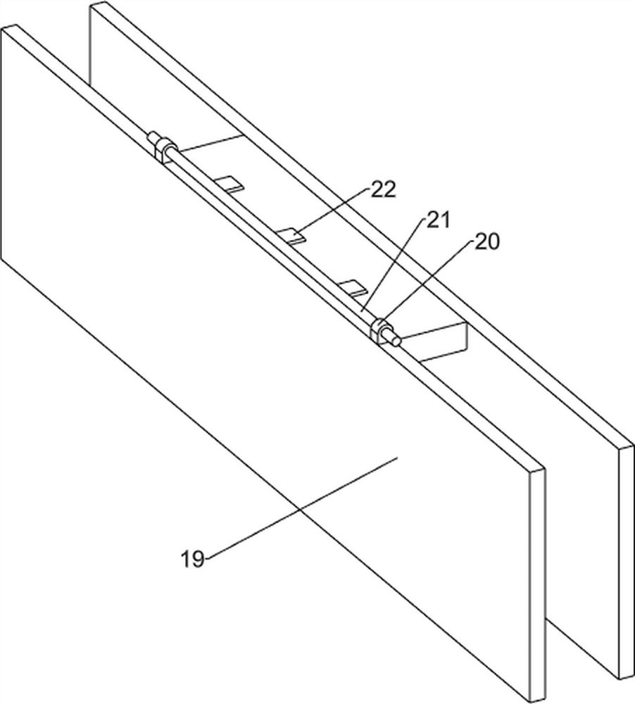
[0028] A bean sprouts auxiliary planting device, such as Figure 1-3 As shown, it includes a support frame 1, a support platform 2, a transmission mechanism 3, a material pushing mechanism 5, a material pushing plate 6, a sand storage bucket 7, a second conveyor belt 8, a first baffle plate 9, a slide plate 10, and a bean storage bucket 11 And stage 12, support frame 1 top right front side is provided with support platform 2, support platform 2 is provided with transmission mechanism 3, support platform 2 top left side is provided with special-shaped plate 4, support frame 1 left front side and transmission mechanism 3 A pusher mechanism 5 is arranged between them, and a pusher plate 6 is arranged on the pusher mechanism 5, and a sand storage bucket 7 is arranged on the left front side of the support frame 1, and two third rotating shafts are connected to the left side of the support frame 1 in a rotary manner, and the third A second conveyor belt 8 is wound around the rotatin...

Embodiment 2

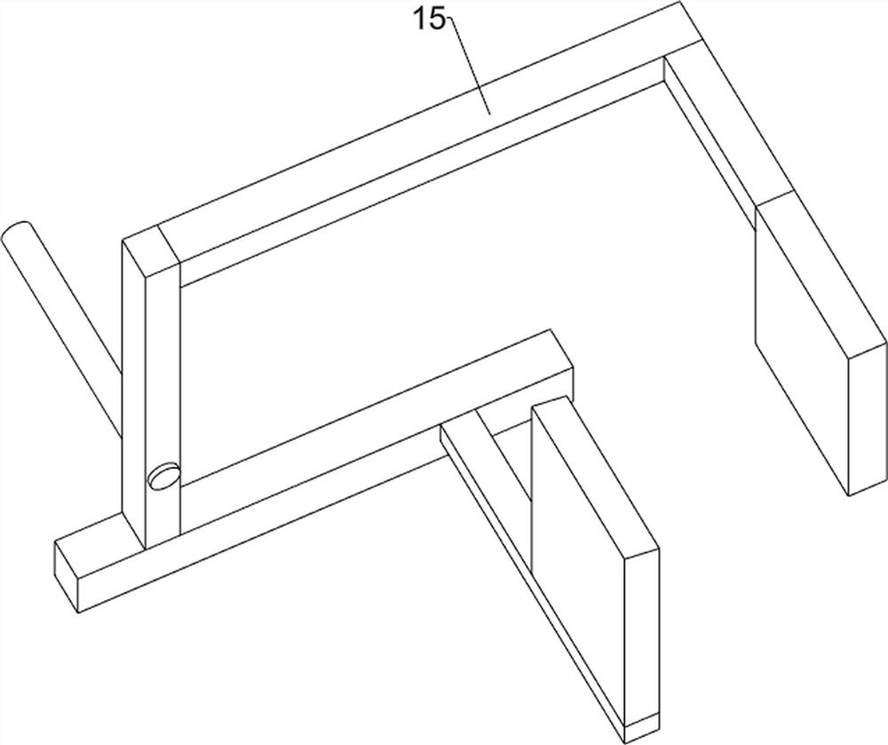
[0033] On the basis of Example 1, such as Figure 4-10 As shown, it also includes a cam 13, a fixed rod 14 and a material partition plate 15. The front side of the first rotating shaft 304 is provided with a cam 13, and the left front side of the support table 2 is rotatably connected with a fixed rod 14. The material plate 15, the material separating plate 15 and the special-shaped plate 4 are slidingly connected.

[0034] The first rotating shaft 304 rotates and drives the cam 13 to constantly rotate. When the cam 13 squeezes the material dividing plate 15, the left side of the material dividing plate 15 is rotated upwards, so that the seedling raising box rotated by the material dividing plate 15 slides out to the left. When the cam 13 When moving away from the material separating plate 15, the material separating plate 15 rotates and resets due to gravity, so that the material separating plate 15 blocks the seedling raising box, and the effect of feeding at intervals can b...


PUM


Abstract

The invention relates to a planting device, in particular to an auxiliary bean sprout planting device. The technical problem of the invention is to provide the bean sprout auxiliary planting device capable of realizing automatic planting and reasonable management of bean sprouts. According to the technical scheme, the bean sprout auxiliary planting device comprises a supporting frame, a supporting table, a conveying mechanism, a pushing mechanism, a pushing plate and a sand storage hopper, the supporting table is arranged on one side of the top of the supporting frame, the conveying mechanism is arranged on the supporting table, a special-shaped plate is arranged on one side of the top of the supporting table, and the pushing mechanism is arranged between one side of the supporting frame and the conveying mechanism. A material pushing plate is arranged on the material pushing mechanism, and a sand storage hopper is arranged on one side of the supporting frame. Through cooperation of the conveying mechanism and the material pushing mechanism, the effect of automatically transporting the seedling raising boxes can be achieved, sand can be firstly laid on the seedling raising boxes in the midway, and then bean sprout seedlings are planted in the seedling raising boxes.

Description

technical field [0001] The invention relates to a planting device, in particular to a bean sprouts auxiliary planting device. Background technique [0002] Planting is one of the main components of agriculture, including the cultivation of various crops, trees, fruit trees, medicinal and ornamental plants, flowers and other horticultural crops, and the bean sprouts planting platform is a technical equipment used by the planting industry to grow bean sprouts . [0003] At present, most of the existing bean sprouts are planted in farmland, it is difficult to rationally manage bean sprouts, it is difficult to plant bean sprouts automatically, and the planting effect of bean sprouts is poor, which seriously affects the output of bean sprouts. Automatic planting and bean sprouts auxiliary planting device that can manage bean sprouts reasonably. Contents of the invention [0004] In order to overcome the shortcomings of the existing bean sprouts planting that it is difficult t...

Claims


Application Information

Patent Timeline
Patent Type & Authority Applications(China)
IPC IPC(8): A01G31/02
CPCA01G31/02Y02P60/21
Inventor 林寿伟
Owner 林寿伟
Why Eureka
Try Eureka