


Quick Research
Generate reliable direction feasibility study reports for your R&D in just a few steps.

Technical Q&A
Discover and master advanced knowledge NOW. Basics, ideas, possibilities, all at once.

Find Solutions
As an expert in R&D theories, this can generate solutions to your technical problems instantly.

Evaluate Feasibility
Analyze your overall solution with one click, know your potential R&D risks in advance.

Monitor Landscape
Get weekly tech updates, stay abreast of the latest tech innovations and key insights.
Circular efficient domestic sewage purifying methane apparatus
A domestic sewage and biogas device technology, which is applied in the direction of aerobic and anaerobic process treatment, can solve the problems of large construction volume and high cost
- Summary
- Abstract
- Description
- Claims
- Application Information
AI Technical Summary
Problems solved by technology
Method used
Image

Examples
Embodiment Construction
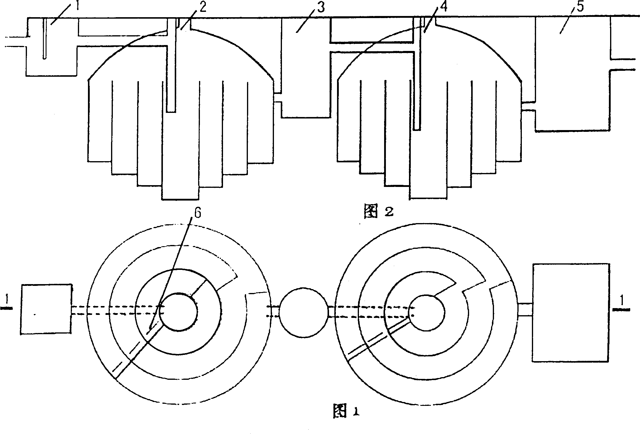
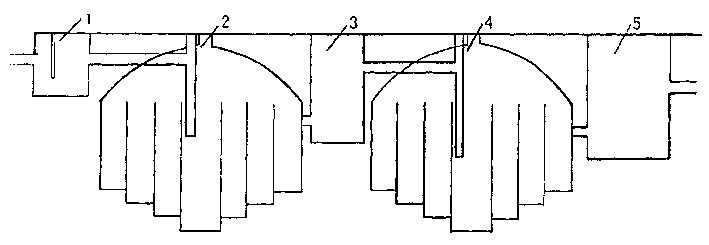
[0009] Figure 1 shows the annular domestic sewage high-efficiency purification biogas device, which consists of a sand trapping well [1], a first-level annular anaerobic tank [2], a sand-settling well [3], a second-level annular anaerobic tank [4], and aerobic The pool [5] is composed. They are connected in sequence through 30 cm diameter water pipes.
[0010] The sand trapping well [1] and the first-level annular anaerobic tank [2] are connected by a cement pipe with a diameter of 30 cm. The grit well [3] is connected to the secondary annular anaerobic tank [4], and the secondary annular anaerobic tank [4] is connected to the aerobic tank [5].
[0011] The structure of the primary annular anaerobic [2] and the secondary annular anaerobic pool [4] are basically the same. They are each composed of a circular ring and a retaining wall sandwiched by several concentric cylinders. The domestic sewage is composed of diameter A 30 cm cement pipe is introduced into the center of the pool....
PUM
 Abstract
Description
Claims
Application Information
 - R&D Engineer
- R&D Manager
- IP Professional
- Industry Leading Data Capabilities
- Powerful AI technology
- Patent DNA Extraction
Browse by: Latest US Patents, China's latest patents, Technical Efficacy Thesaurus, Application Domain, Technology Topic, Popular Technical Reports.
© 2024 PatSnap. All rights reserved.Legal|Privacy policy|Modern Slavery Act Transparency Statement|Sitemap|About US| Contact US: help@patsnap.com