
Detector and classified audio signal automatic gain control device

An automatic gain control and audio signal technology, applied in the direction of sensors, transducer circuits, sensor components, etc., can solve problems such as poor integration and pertinence, poor consistency of analog signal processing, and affecting the modulation degree of audio broadcasting transmission equipment. Achieve the effect of improving efficiency and improving broadcasting effect

Active Publication Date: 2022-03-01
BEIJING BBEF SCI & TECH
View PDF7 Cites 1 Cited by
  • Summary
  • Abstract
  • Description
  • Claims
  • Application Information

AI Technical Summary

Problems solved by technology

[0002] During the broadcasting of audio programs, different programs or large differences in sound loudness in the same program will affect the modulation degree of audio broadcasting transmitting equipment, so that the transmitter cannot The audio signal is transmitted with a relatively balanced modulation degree, resulting in waste of power, and the user's listening effect is not good; the current amplitude control of the audio signal is mainly divided into two categories, one is the use of analog circuits, and the method of analog envelope tracking is added. Automatic gain control to achieve the purpose of controlling the signal amplitude; the second type is to use a professional audio processor to control the gain of the sound signal
However, the former cannot process digital audio signals, and has poor consistency in the processing of analog signals, and has the defect of amplifying noise together, and it is also inconvenient to adjust the audio amplitude; the latter, although the audio processor has comprehensive functions, is expensive. Poor integration and pertinence

Method used


Image

  • Detector and classified audio signal automatic gain control device
  • Detector and classified audio signal automatic gain control device
  • Detector and classified audio signal automatic gain control device

Examples


Embodiment Construction

[0043] The technical solutions of the present invention will be clearly and completely described below in conjunction with the embodiments. Obviously, the described embodiments are part of the embodiments of the present invention, but not all of them. Based on the embodiments of the present invention, all other embodiments obtained by persons of ordinary skill in the art without making creative efforts belong to the protection scope of the present invention.

[0044] The present invention will be further described below in conjunction with accompanying drawing description and specific embodiment:

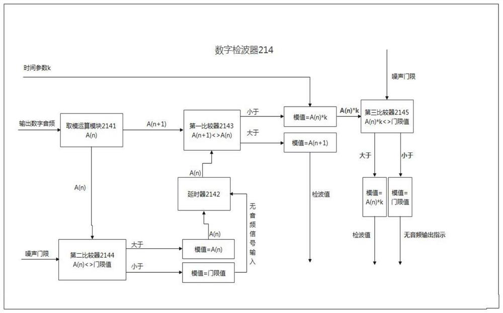
[0045] figure 1 A schematic diagram of the implementation of a digital detector 214 according to an embodiment of the present invention is shown, as figure 1 As shown, the digital detector 214 includes:

[0046] A modulo calculation module 2141, which is used to obtain a digital audio signal and perform a modulo operation to obtain a value after the modulo operation;

[0047] Del...


PUM


Abstract

The invention provides a digital detector, and the detector comprises a modulo operation module which is used for obtaining a digital audio signal and carrying out the modulo operation, and obtaining a value after the modulo operation; the delayer is used for delaying an envelope signal of one period of a current amplitude envelope value, and transmitting a first value obtained by first operation of the modular operation module to the first comparator; the first comparator is used for receiving the first value and a second value obtained by second operation of the modulo operation module, and comparing the first value with the second value; the second comparator is used for receiving the first value and a noise threshold value and comparing the first value with the noise threshold value; the third comparator is used for receiving a product of the first value and a time parameter and a noise threshold value, and comparing the product of the first value and the time parameter and the noise threshold value; according to the invention, rapid detection and noise threshold setting can be realized to prevent noise signal output, so that the efficiency and the broadcasting effect are improved.

Description

technical field [0001] The invention relates to the field of audio signal processing, in particular to a wave detector, a classification audio processing device, a classification audio signal automatic gain control device, a transmitter and a classification audio signal automatic gain control method. Background technique [0002] During the broadcasting of audio programs, different programs or large differences in sound loudness in the same program will affect the modulation degree of the audio broadcasting transmitting equipment, so that the transmitter cannot transmit audio signals with a relatively balanced modulation degree, resulting in waste of power. The listening effect is not good; the current amplitude control of the audio signal is mainly divided into two categories, one is the use of analog circuits, the analog envelope tracking method plus automatic gain control to achieve the purpose of controlling the signal amplitude; the second category is A professional aud...

Claims


Application Information

Patent Timeline
IPC IPC(8): H04B1/04H04R3/00
CPCH04B1/04H04R3/00
Inventor 梁富林张百川高振中龙平
Owner BEIJING BBEF SCI & TECH
Learn More