
Distributed photovoltaic power generation device

A distributed photovoltaic and power generation device technology, applied in photovoltaic power generation, photovoltaic modules, solar thermal power generation and other directions, can solve the problems of reducing the reliability of distributed photovoltaic power generation devices, prone to mud spots on photovoltaic panels, and impact on power generation work, etc. High practicability, dust reduction, and work load reduction effect

Inactive Publication Date: 2022-03-01
刘俊
View PDF0 Cites 0 Cited by
  • Summary
  • Abstract
  • Description
  • Claims
  • Application Information

AI Technical Summary

Problems solved by technology

[0003] When the existing distributed photovoltaic power generation device is working, when it encounters rainy weather, because there is no measure to keep out the rain, the rainwater directly drops on the photovoltaic panel, which leads to the phenomenon of mud spots on the photovoltaic panel, which is harmful to the environment. Not only that, after the existing distributed photovoltaic power generation device works for a long time, the phenomenon of dust accumulation on the photovoltaic panel is easy to appear, thus blocking the sunlight and affecting the power generation rate, thereby reducing the actual The reliability of some distributed photovoltaic power generation devices

Method used


Image

  • Distributed photovoltaic power generation device
  • Distributed photovoltaic power generation device
  • Distributed photovoltaic power generation device

Examples


Embodiment Construction

[0022] The present invention is described in further detail now in conjunction with accompanying drawing. These drawings are all simplified schematic diagrams, which only illustrate the basic structure of the present invention in a schematic manner, so they only show the configurations related to the present invention.

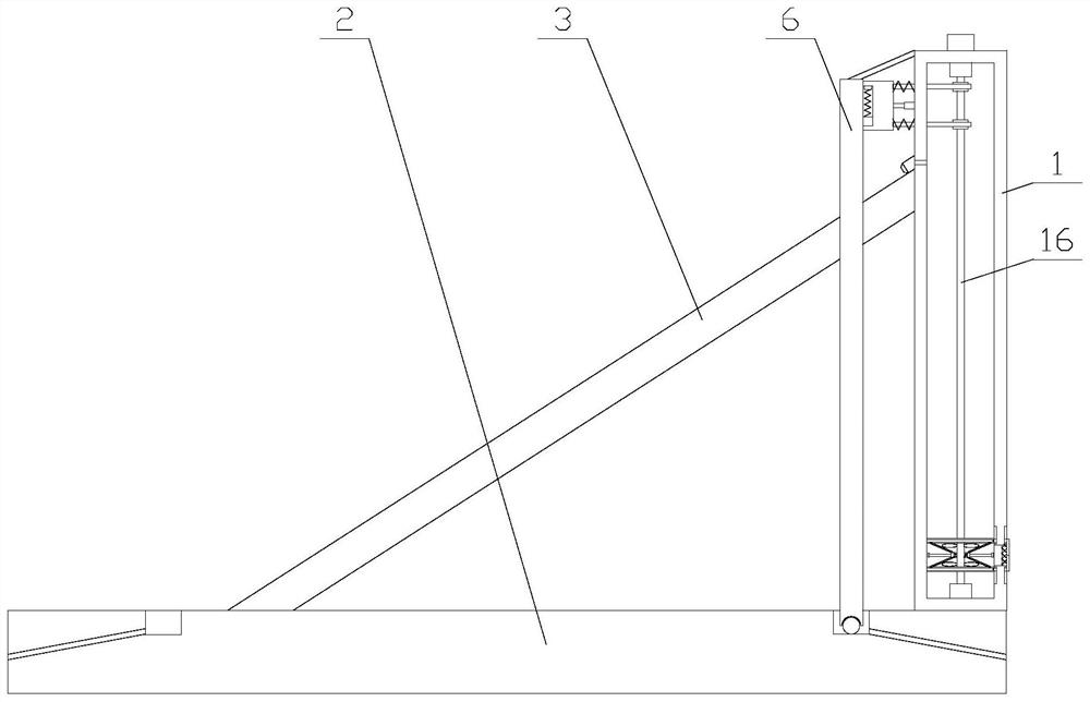
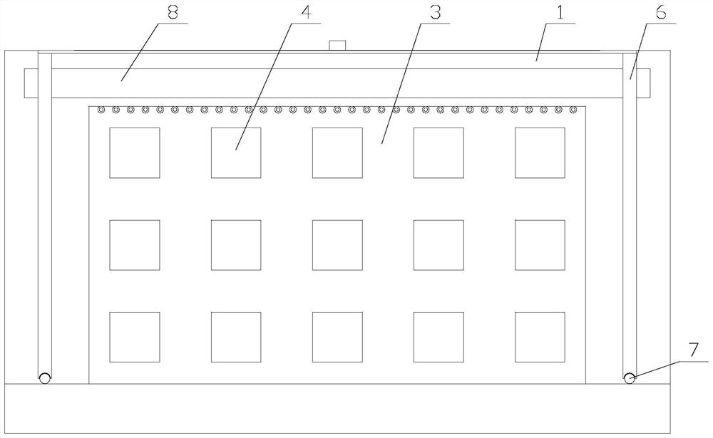
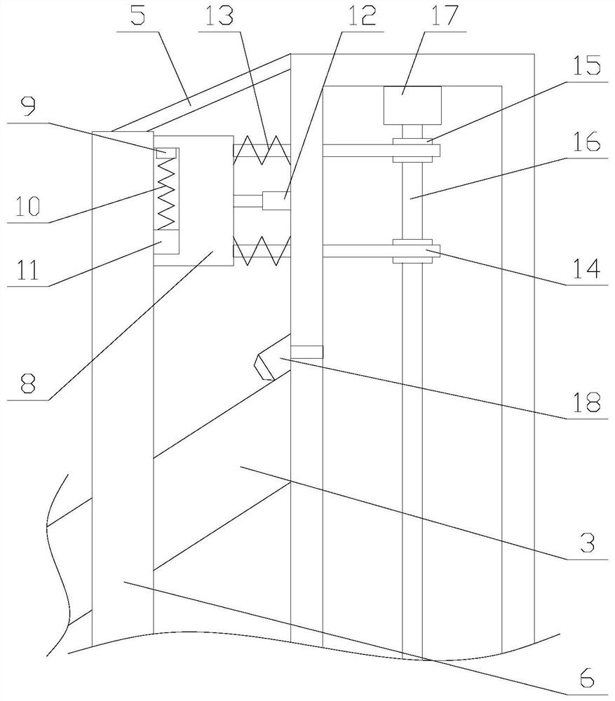
[0023] Such as Figure 1-2 As shown, a distributed photovoltaic power generation device includes a base plate 2, a support box 1, a substrate 3 and several photovoltaic panels 4, the support box 1 is arranged on the upper side of the base plate 2, and the two ends of the base plate 3 are respectively It is connected to one side of the support box 1 and the top of the bottom plate 2, and each photovoltaic panel 4 is evenly arranged on the base plate 3. The inside of the support box 1 is provided with a PLC, and also includes a rain-shielding mechanism and a dust-removing mechanism. The rain-shielding mechanism Connect with the dust removal mechanism;

[0024]...


PUM


Abstract

The invention relates to a distributed photovoltaic power generation device which comprises a bottom plate, a supporting box, a base plate and a plurality of photovoltaic panels and further comprises a rain shielding mechanism and a dust removal mechanism, the rain shielding mechanism comprises a driving assembly, a raindrop sensor, a connecting strip, rain shielding cloth, two limiting assemblies and two connecting assemblies, and each limiting assembly comprises a limiting rod, a lifting unit and a ball. The dust removal mechanism comprises a filter screen, a dustproof assembly, two stirring assemblies and a plurality of nozzles, the dustproof assembly comprises two dustproof plates, two moving units and a plurality of power units, the distributed photovoltaic power generation device achieves the purpose of shielding rain through the rain shielding mechanism, the probability that rainwater falls on a photovoltaic panel is reduced, and the reliability of the distributed photovoltaic power generation device is improved. According to the photovoltaic power generation device, mud points are prevented from appearing on the photovoltaic panel, the influence on photovoltaic power generation work is avoided, the dust removal function of the photovoltaic panel is achieved through the dust removal mechanism, the phenomenon of dust accumulation on the photovoltaic panel is prevented, and therefore sunlight cannot be shielded, and the power generation rate cannot be influenced.

Description

technical field [0001] The invention relates to the field of photovoltaic power generation, in particular to a distributed photovoltaic power generation device. Background technique [0002] Distributed photovoltaic power generation specifically refers to photovoltaic power generation facilities that are built near the user's site, and whose operation mode is characterized by self-consumption on the user side, surplus electricity connected to the grid, and balanced adjustment in the power distribution system. Distributed photovoltaic power generation follows the principles of adapting measures to local conditions, clean and efficient, decentralized layout, and nearby utilization, making full use of local solar energy resources to replace and reduce fossil energy consumption. [0003] When the existing distributed photovoltaic power generation device is working, when it encounters rainy weather, because there is no measure to keep out the rain, the rainwater directly drops on...

Claims


Application Information

Patent Timeline
IPC IPC(8): H02S40/10B01D46/10B08B5/02H02S40/30F24S40/20F24S40/44
CPCH02S40/10B01D46/10B08B5/02H02S40/30F24S40/20F24S40/44Y02E10/40Y02E10/50
Inventor 刘俊
Owner 刘俊
Learn More