
Determination of power line failure

A power line and fault technology, applied in the field of determination of power line faults

Pending Publication Date: 2022-03-01
HITACHI ENERGY SWITZERLAND AG
View PDF1 Cites 0 Cited by
  • Summary
  • Abstract
  • Description
  • Claims
  • Application Information

AI Technical Summary

Problems solved by technology

However, there is still room for improvement

Method used


Image

  • Determination of power line failure
  • Determination of power line failure
  • Determination of power line failure

Examples


Embodiment Construction

[0061] Embodiments of the invention are discussed in detail below. In describing the embodiments, specific terminology is used for the sake of clarity. However, the invention is not limited to the specific terms chosen. While specific exemplary embodiments are discussed, it should be understood that this is done for illustration purposes only. A person skilled in the relevant art will recognize that other components and configurations may be used without departing from the spirit and scope of the invention.

[0062] The present invention generally relates to the handling of faults in power lines.

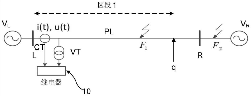
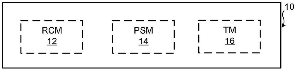
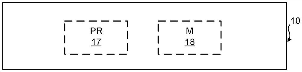
[0063] figure 1 Schematically shows a first local voltage source V connected at a local point L L and a second voltage source V at the remote point R R Power line PL between two voltage sources. At the local point L there are also devices for determining power line faults. In the present example, the device is realized as a protective relay 10 connected to the power line PL a...


PUM


Abstract

A method of determining a fault in a protected section of a power line, comprising: acquiring (20) a measurement at a measurement point at one end of the power line; the measurement results are processed in a plurality of parallel processing branches comprising at least two parallel processing branches, where the processing in each branch comprises: filtering the measurement results in a respective low pass filter (LPF1, LPF2, LPFN) to obtain a respective set of filtered measurement results, where the cut-off frequencies (f1, f2, f3) of the low pass filters in the parallel processing branches are different from the cut-off frequencies (f1, f2, f3) of the low pass filters in the parallel processing branches. The method comprises filtering measurements (S1, S2, SN, fN) different from each other, performing a range calculation (28, 30, 32) on the filtered measurements to obtain respective range point quantities (QSQ1, QSQ2, QSQN), and comparing (34, 36, 38) the range point quantities (QSQ1, QSQ2, QSQN) with respective thresholds (S1, S2, SN). Finally, if any threshold value is exceeded, it is determined that a fault is present in the protected section (40).

Description

technical field [0001] The present invention generally relates to the determination of power line faults. The invention more particularly relates to a method, device, and computer program product for determining power line faults. Background technique [0002] Determining faults in power lines is an important aspect in power transmission and distribution systems. There are several different ways to achieve this, for example, using phasor domain based distance protection. [0003] A scheme worth using is the time-domain distance protection scheme described in WO 2017 / 177424. Compared with the protection scheme based on phasor domain, this scheme has the advantage of high speed. However, there is still room for improvement. [0004] Aspects of the invention aim to improve temporal distance protection schemes. Contents of the invention [0005] It is an object of the present invention to improve temporal distance protection schemes. [0006] According to a first aspect,...

Claims


Application Information

Patent Timeline
IPC IPC(8): G01R31/08
CPCG01R31/083G01R31/088H02H3/38H02H3/05H02H7/26G01R31/52G01R19/2513G01R19/16576G01R31/085
Inventor 李幼仪王建平
Owner HITACHI ENERGY SWITZERLAND AG
Learn More