Sensor environment temperature measuring circuit and sensor
A technology of ambient temperature and measurement circuit, applied in the field of sensors, can solve problems such as poor precision and complex system, and achieve the effects of improved precision, accurate temperature measurement and compact structure
- Summary
- Abstract
- Description
- Claims
- Application Information
AI Technical Summary
Problems solved by technology
Method used
Image
Examples
Embodiment 1
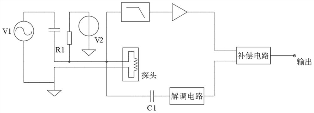
[0039] like Figure 4As shown, this embodiment is an application of the present invention to a single-probe eddy current sensor. The displacement measurement circuit is composed of excitation source V1, detection bridge and demodulation circuit. The AC excitation voltage V1 is divided between R1 and the probe. The amplitude and phase of the AC voltage change with the distance between the probe and the target board. Displacement information can be obtained by processing the voltage. Use an operational amplifier to add a DC bias V2 at the excitation terminal. The DC bias circuit is an addition circuit composed of a DC voltage source or an operational amplifier directly connected in series with the AC excitation source. The DC voltage is superimposed on the AC voltage. The addition circuit is conventional. Technology, I won’t go into details here, as long as it is guaranteed, the DC voltage can be superimposed on the AC voltage. The DC voltage is divided on the resistance R1 of ...
Embodiment 2
[0042] Such as Figure 5 As shown, this embodiment is the application of the present invention on the differential eddy current sensor. The measurement circuit is composed of excitation source V1, detection bridge, and demodulation circuit. The AC excitation voltage V1 is divided on R1 and probe 1, and at the same time, it is divided on R3 and probe 2. The amplitude and phase of the two voltages follow the probe. The distance from the target board changes, and the displacement information can be obtained by making a difference between the two and demodulating. A DC bias V2 is added at the excitation end, and the DC voltage is divided on the resistance R1 of the bridge and the DC resistance of the probe 1, and then amplified after low-pass filtering to obtain a voltage reflecting the temperature of the probe. R1 and R3 use low-temperature drift resistors, and the low-temperature drift coefficient can avoid the temperature drift at the conditioning circuit from affecting the te...
Embodiment 3
[0044] This embodiment is an application of the present invention to a differential transformer sensor. In this embodiment, the exciting coil of the differential transformer sensor is used as the temperature measuring element. Add a DC bias V2 and a voltage divider resistor R1 at the excitation end. The DC voltage is divided on the resistor R1 and the DC resistance of the probe excitation coil, amplified after low-pass filtering, and a voltage reflecting the temperature of the probe is obtained. Among them, R1 should use a low-temperature drift resistor to avoid the temperature drift at the conditioning circuit from affecting the temperature measurement of the probe; the input impedance of the filter should be much larger than the probe impedance, so as to avoid the impact of shunt on displacement measurement.
[0045] The compensation methods of the above-mentioned sensors are only some of them, and the other types are only the compensation of inductive sensors. All can be i...
PUM
 Abstract
Description
Claims
Application Information
 - R&D Engineer
- R&D Manager
- IP Professional
- Industry Leading Data Capabilities
- Powerful AI technology
- Patent DNA Extraction
Browse by: Latest US Patents, China's latest patents, Technical Efficacy Thesaurus, Application Domain, Technology Topic, Popular Technical Reports.
© 2024 PatSnap. All rights reserved.Legal|Privacy policy|Modern Slavery Act Transparency Statement|Sitemap|About US| Contact US: help@patsnap.com


