LED plant lamp radiating surface adjusting mechanism and adjusting method thereof

A technology of LED plant lamps and adjustment mechanisms, applied in botany equipment and methods, horticultural methods, refractors, etc., can solve the problems of insufficient uniformity of plant radiation and high cost, and achieve increased irradiation range, weakened irradiation intensity, and uniform dispersion The effect of the light source

Active Publication Date: 2022-03-01
深圳市桑瑞生物科技有限公司
View PDF5 Cites 1 Cited by
  • Summary
  • Abstract
  • Description
  • Claims
  • Application Information

AI Technical Summary

Problems solved by technology

[0003] Existing LED plant growth lamps are usually installed evenly along the length of the plant frame. After installation, the radiation surface of the LED plant growth lamp faces the direction of planting. The installation method of this LED plant growth lamp is often costly and does not It is possible to switch the radiation surface of the LED plant light, which may easily cause the plant radiation to be uneven. In the prior art, there are LED plant lights that can change the radiation surface, but there is no automatic switching, no manual operation, multiple angles, multiple light-transmitting panels, and Plant lamps that provide signals of different light wavelengths, which can be adjusted to specific emission wavelengths, are conducive to studying the sensitivity and absorption efficiency of different plants to specific wavelengths of light

Method used


Image

  • LED plant lamp radiating surface adjusting mechanism and adjusting method thereof
  • LED plant lamp radiating surface adjusting mechanism and adjusting method thereof
  • LED plant lamp radiating surface adjusting mechanism and adjusting method thereof

Examples


Embodiment Construction

[0044] In order to make the purpose, technical solutions and advantages of the embodiments of the present invention more clear, the technical solutions in the embodiments of the present invention will be clearly and completely described below in conjunction with the accompanying drawings in the embodiments of the present invention. Obviously, the described embodiments It is a part of embodiments of the present invention, but not all embodiments. Based on the embodiments of the present invention, all other embodiments obtained by persons of ordinary skill in the art without making creative efforts belong to the protection scope of the present invention.

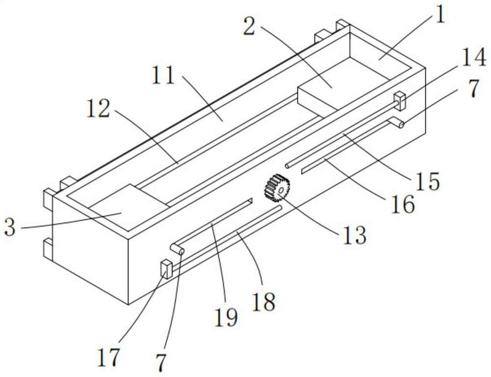
[0045] The embodiment of the present invention proposes a radiation surface adjustment mechanism for LED plant lights, including a guide assembly 1, a drive assembly 4, a flip assembly 5 and a radiation assembly 6; for example, figure 1 shown.

[0046] One side of the inner wall of the guide assembly 1 is slidably connected wit...


PUM


Abstract

The invention belongs to the technical field of LED plant lamps, and particularly relates to an LED plant lamp radiating surface adjusting mechanism and an adjusting method thereof.The LED plant lamp radiating surface adjusting mechanism comprises a guiding assembly, a driving assembly, an overturning assembly and a radiating assembly; the outer side wall of the first lamp and the outer side wall of the second lamp are both rotationally connected with guide columns, the guide columns on the first lamp extend into the first hollow sliding cavity and the second hollow sliding cavity correspondingly, and the guide columns on the second lamp extend into the first hollow sliding cavity and the third hollow sliding cavity correspondingly. The bottom end of the driving gear is in engaged connection with a first rack, and the end part of the first rack is in transmission connection with the end parts of one group of guide columns through a first linkage block; the effect of synchronously driving the first bent rod and the second bent rod to rotate on the same side is achieved through rotation of the double-shaft servo motor, the effect of overturning and adjusting the radiation assembly is achieved, and the effect that the radiation assembly provides different radiation states for the first lamp and the second lamp is achieved.

Description

technical field [0001] The invention belongs to the technical field of LED plant lamps, and in particular relates to an LED plant lamp radiation surface adjustment mechanism and an adjustment method thereof. Background technique [0002] LED plant light, also known as LED plant growth light, is an artificial light source that uses LED light-emitting diodes as illuminants to meet the lighting conditions required for plant photosynthesis. In an environment that lacks sunlight, this lamp can act as sunlight to enable plants to grow normally or better. This lamp has the functions of strengthening roots, promoting growth, regulating flowering period and flower color, promoting fruit ripening and coloring, and improving taste and quality. effect. [0003] Existing LED plant growth lamps are usually installed evenly along the length of the plant frame. After installation, the radiation surface of the LED plant growth lamp faces the direction of planting. The installation method of...

Claims


Application Information

Patent Timeline
Patent Type & Authority Applications(China)
IPC IPC(8): F21S2/00F21V5/00F21V14/06F21V17/02A01G7/04F21Y115/10
CPCF21S2/00F21V17/02F21V14/06F21V5/00A01G7/045F21Y2115/10Y02P60/14
Inventor 王振华雷斌
Owner 深圳市桑瑞生物科技有限公司
Why Eureka
Try Eureka