
Electronic assembly for illuminating a target area marking a detection area of a sensor

An electronic component and detection range technology, applied in the field of electronic components, can solve the problem that it is difficult for the operator to identify the target range

Active Publication Date: 2017-02-22
HUF HULSBECK & FURST GMBH & CO KG
View PDF9 Cites 0 Cited by
  • Summary
  • Abstract
  • Description
  • Claims
  • Application Information

AI Technical Summary

Problems solved by technology

[0004] Especially in the case of uneven ground, such as when a motor vehicle is parked on the lawn, it is difficult for the operator to identify the target range marked with the white light

Method used


Image

  • Electronic assembly for illuminating a target area marking a detection area of a sensor
  • Electronic assembly for illuminating a target area marking a detection area of a sensor
  • Electronic assembly for illuminating a target area marking a detection area of a sensor

Examples


Embodiment Construction

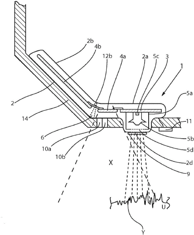
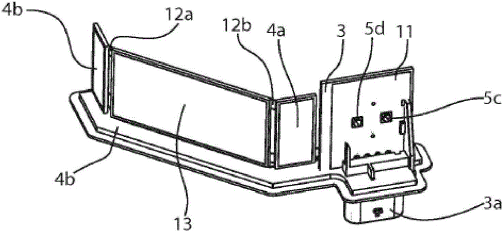
[0020] figure 1 A side sectional view of a first exemplary embodiment of an electronic assembly 1 is shown, which is fastened to a body component 14 of a motor vehicle. In the exemplary embodiment shown, the electronics assembly comprises a housing 2 with two housing sections 2 a and 2 b , which are connected to one another via a joint region 6 .

[0021] Different further components are arranged in the two housing sections 2 a , 2 b of the electronics module according to the first exemplary embodiment of the invention. A control and evaluation device 3 is also arranged in the housing section 2 a and has an illumination device 5 a coupled thereto. The lighting device 5a comprises a lamp 5c in this embodiment. The lighting device 5a also includes a transparent through hole 5b through which the light emitted by the lamp 5c can pass. The target area Y is marked on the ground U by means of the luminaire 5c. The lighting device 5a is equipped with a lens structure 5b, which is ...


PUM


Abstract

The invention relates to an electronic assembly for illuminating a target area marking a detection area of a sensor. It is often difficult for the operator to detect the target area by means of conventional electronic assemblies if the underlying surface is uneven. In order to solve this problem, an assembly according to the invention has a housing (2), in which a control and evaluation device (3) is arranged, which can be coupled with a control device of the motor vehicle. The electronic assembly further comprises an illumination device (5a) that is coupled with the control and evaluation device and can be controlled by the latter, by means of which a target area identifying a detection area outside the housing can be marked on the underlying surface by means of an optical signal. According to the invention, the illumination device can be actuated by the control and evaluation device to emit light of different colors.

Description

technical field [0001] The invention relates to an electronic assembly for a motor vehicle, in particular to an electronic assembly for illuminating a target field marking the detection range of a sensor. Background technique [0002] In order to be able to operate the doors or the trunk of the motor vehicle without contact, the user usually makes a holding gesture within a defined area of ​​the motor vehicle in order to initiate the actuation of the doors or the trunk. In order to open the trunk of the motor vehicle, the user usually places his foot in the area below the bumper and, if necessary, makes a sideways movement there. [0003] In order to inform the operator of the detection range of the sensor which detected the presence of the operator's foot, the range is marked on the ground by means of lighting, for which purpose white light is used according to the prior art. [0004] Especially in the case of uneven ground, such as when a motor vehicle is parked on a lawn...

Claims


Application Information

Patent Timeline
Patent Type & Authority Applications(China)
IPC IPC(8): B60Q1/32B60Q1/50H05B44/00
CPCB60Q1/323B60Q1/50B60Q2400/50H05B45/20F21V5/04Y02B20/40H05B45/22H05B47/11B60Q1/247F21Y2113/13F21Y2115/10B08B3/02B60Q2400/20B60Q2400/40
Inventor M·约姆基尔B·艾特S·莫尼夫H·舒马赫N·斯蒂克林I·林迪克N·赫勒A·齐格勒C·哈克O·姆勒M·香德勒
Owner HUF HULSBECK & FURST GMBH & CO KG
Learn More