Bill data binding device and operation method

A bill and data technology, applied in the field of bill data binding device, can solve the problems of affecting the binding quality, inconvenience for financial personnel, and different sizes

Inactive Publication Date: 2022-03-01
黑龙江省农业科学院水稻研究所
View PDF0 Cites 0 Cited by
  • Summary
  • Abstract
  • Description
  • Claims
  • Application Information

AI Technical Summary

Problems solved by technology

[0002] In the process of binding bills, due to the many specifications and different sizes of bills, each bill needs to be punched for binding, which not only brings great inconvenience to financial personnel, but also affects the quality of binding because of irregular punching. more than one punching device

Method used


Image

  • Bill data binding device and operation method
  • Bill data binding device and operation method
  • Bill data binding device and operation method

Examples


Embodiment Construction

[0027] Below according to accompanying drawing and embodiment the present invention will be described in further detail:

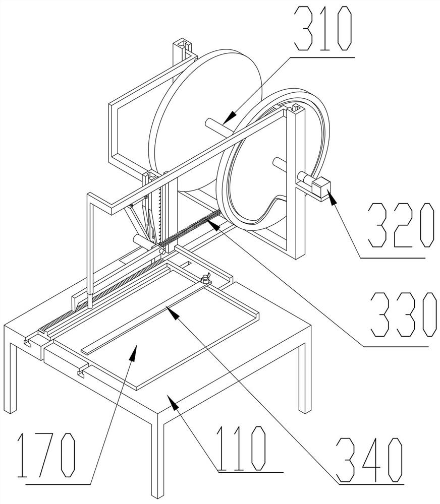
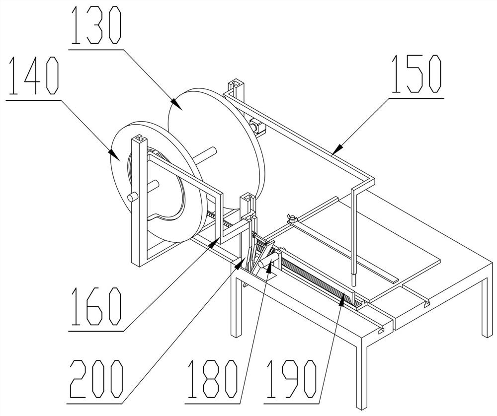
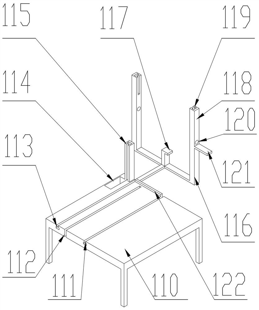
[0028] A bill data binding device, comprising a frame 110, a right cam 130, a left cam 140, a right slider 150, a left slider 160, a positioning plate 170, a power slider 180, a pawl 190, a distance adjusting device 200, and a distance adjusting The device 200 includes a distance adjusting seat 210, an inclined plate 220, and an adjustment slider 230. There is a central chute 111 in the middle of the frame 110, a rack notch 112 is provided on the left side of the central chute 111, and a rack notch 112 is provided on the left side of the rack notch 112. Left chute 113, frame 110 rear side has baffle plate 122, frame 110 left side rear has rear chute 115, rear chute 115 front side has square hole 114, left chute 113 rear side has connecting frame 116, There is a spring frame 117 in the middle of the connecting frame 116. There are two symmetrical columns 11...


PUM


Abstract

The bill data binding device comprises a rack, a right cam, a left cam, a right sliding block, a left sliding block, a positioning plate, a power sliding block, a pawl and a distance adjusting device, the distance adjusting device comprises a distance adjusting base, an inclined plate and an adjusting sliding block, a center sliding groove is formed in the middle of the rack, a rack notch is formed in the left side of the center sliding groove, and a left sliding groove is formed in the left side of the rack notch. A square hole is formed in the front side of the rear sliding groove. A connecting frame is arranged on the rear side of the left sliding groove. A spring frame is arranged in the middle of the connecting frame. Two symmetrical stand columns are arranged on the left side and the right side of the connecting frame. A stand column sliding groove is formed in the middle of the upper portion of each stand column, a shaft hole is formed in the middle of each stand column, and a motor plate is arranged on the lower portion of the shaft hole on the right side.

Description

technical field [0001] The invention relates to the field of data binding, in particular to a bill data binding device and an operation method. Background technique [0002] In the process of binding bills, due to the many specifications and different sizes of bills, each bill needs to be punched for binding, which not only brings great inconvenience to financial personnel, but also affects the quality of binding because of irregular punching. A punching device above the requirements. Contents of the invention [0003] Aiming at the above-mentioned deficiencies in the prior art, the present invention provides a bill data binding device and an operation method that are adaptable to various bill specifications, with adjustable hole spacing and automatic drilling. [0004] The purpose of the present invention is to realize through the following technical solutions: [0005] A bill data binding device, including a frame, a right cam, a left cam, a right slider, a left slider...

Claims


Application Information

Patent Timeline
Patent Type & Authority Applications(China)
IPC IPC(8): B26F1/02B26D5/16B26D7/02B26D7/26
CPCB26F1/02B26D5/16B26D7/025B26D7/015B26D7/2628
Inventor 李秀敏迟铭韦国婷
Owner 黑龙江省农业科学院水稻研究所
Why Eureka
Try Eureka