Welding device for metal structural part

A technology for metal structural parts and welding devices, applied in auxiliary devices, welding equipment, auxiliary welding equipment, etc., can solve the problems of poor quality of welding joints and low welding efficiency, and achieve stable welding points, improve efficiency, and improve welding action. consistent effect

Active Publication Date: 2022-03-01
深圳亚士德科技有限公司
View PDF6 Cites 0 Cited by
  • Summary
  • Abstract
  • Description
  • Claims
  • Application Information

AI Technical Summary

Problems solved by technology

[0003] At present, most of the manufacturers in the production of ladders use manual welding, which not only has low welding efficiency, but also has poor quality of welded joints.

Method used


Image

  • Welding device for metal structural part
  • Welding device for metal structural part
  • Welding device for metal structural part

Examples


Embodiment 1

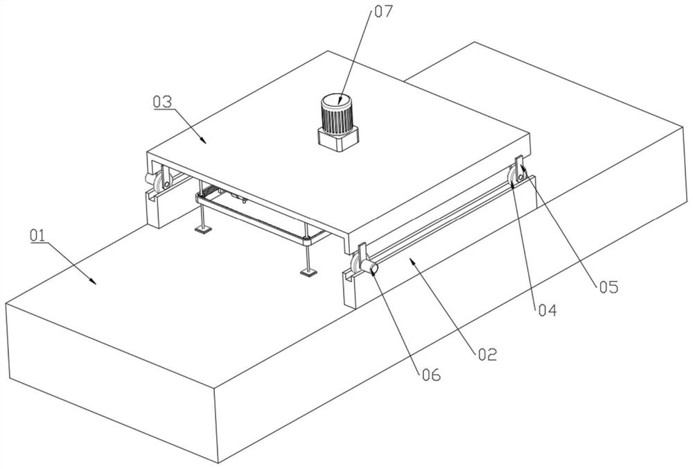
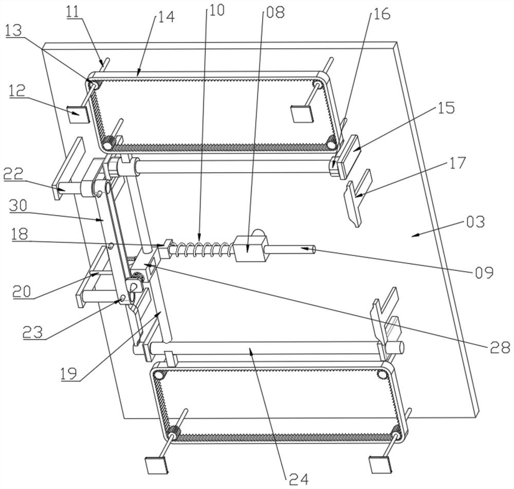
[0026] see Figure 1 to Figure 6 , a welding device for metal structural parts, including a sliding bed 03, the lower surface of the sliding bed 03 is provided with a welding device, the welding device includes a driving shaft 27 that is rotatably connected to the sliding bed 03, and the lower surface of the driving shaft 27 is fixedly connected with Rotating block 08, the upper limit of rotating block 08 is slidably connected with sliding rod 09, and one end of sliding rod 09 close to length limiting rod 19 is fixedly connected with connecting block 18, and the outer wall of sliding rod 09 is located in the outer wall sleeve between rotating block 08 and connecting block 18 A spring 10 is provided, and the connecting block 18 is fixedly rotatably connected with a sliding seat 28. The sliding seat 28 is slidably connected to the length-limiting rod 19. The lower surface of the sliding seat 28 is provided with a welding torch head 32 for welding, and the upper surface of the sli...

Embodiment 2

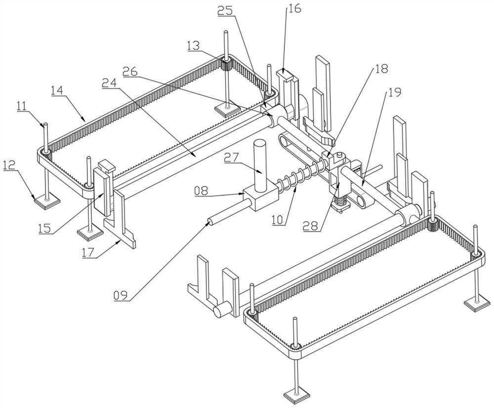
[0044] see Figure 7 As another embodiment of the post-welding processing device, the post-welding processing device includes a connecting block two 25 fixedly connected to the width-limiting rod 24 on the side away from the derusting device, and a toothed belt 14 is fixedly connected to the connecting block two 25, sliding The lower surface of the bed 03 is rotatably connected with a rotating rod 11, and the rotating rod 11 is fixedly connected with a gear 13. Four rotating rods 11 are arranged in a rectangular distribution, and the lower end of the rotating rod 11 is fixedly connected with a cylindrical cam 41. The lower surface of the sliding bed 03 The second mounting plate 40 is fixedly connected, and the lower end of the second mounting plate 40 is slidingly connected with a hammer rod 39. The lower end of the hammer rod 39 is provided with a part with a diameter larger than the whole body. The protruding rod 42 that moves up and down.

[0045] The driving principle is ...


PUM


Abstract

The invention discloses a welding device for metal structural parts, which comprises a sliding bed, a welding device is arranged on the lower surface of the sliding bed, the welding device comprises a driving shaft rotationally connected to the sliding bed, a rotating block is fixedly connected to the lower surface of the driving shaft, and a sliding rod is slidably connected to the upper limit of the rotating block. The end, close to the length limiting rod, of the sliding rod is fixedly connected with a first connecting block, the outer wall, located between the rotating block and the first connecting block, of the sliding rod is sleeved with a first spring, the connecting block is rotationally connected with a sliding base through a fixed shaft, the sliding base is slidably connected with the length limiting rod, and a welding gun head used for welding is arranged on the lower surface of the sliding base. The upper surface of the sliding bed is fixedly connected with a servo motor capable of driving the driving shaft to rotate. The welding device further comprises a rectangular limiting device for limiting the welding device. According to the automatic welding device, full-automatic welding can be achieved, the welding efficiency is high, and welding spots after welding are more stable.

Description

technical field [0001] The invention relates to the technical field of welding technology, in particular to a welding device for metal structural parts. Background technique [0002] The herringbone ladder is a kind of metal component, a kind of climbing tool used for decoration in the space above the plane (such as the roof). It is mainly composed of welding a plurality of step segments on the ladder beam. [0003] At present, most of the manufacturers of ladder ladders are manually welded, which not only has low welding efficiency, but also has poor quality of welded joints. Contents of the invention [0004] The purpose of the present invention is to provide a welding device for metal structural parts, which has the advantages of fully automatic welding, not only high welding efficiency, but also more stable welding position after welding, and solves the problems in the background technology. [0005] In order to achieve the above object, the present invention provide...

Claims


Application Information

Patent Timeline
Patent Type & Authority Applications(China)
IPC IPC(8): B23K37/00B23K37/08
CPCB23K37/00B23K37/08
Inventor 胡鹏周行
Owner 深圳亚士德科技有限公司
Why Eureka
Try Eureka