
Method for checking airtightness of closed cavity

An air-tightness inspection and air-tightness technology, which can be used in liquid/vacuum measurement for liquid-tightness measurement, and by measuring the acceleration and deceleration rate of fluids, which can solve problems such as the inability to quantitatively evaluate the degree of sealing.

Pending Publication Date: 2022-02-25
AECC COMML AIRCRAFT ENGINE CO LTD
View PDF0 Cites 0 Cited by
  • Summary
  • Abstract
  • Description
  • Claims
  • Application Information

AI Technical Summary

Problems solved by technology

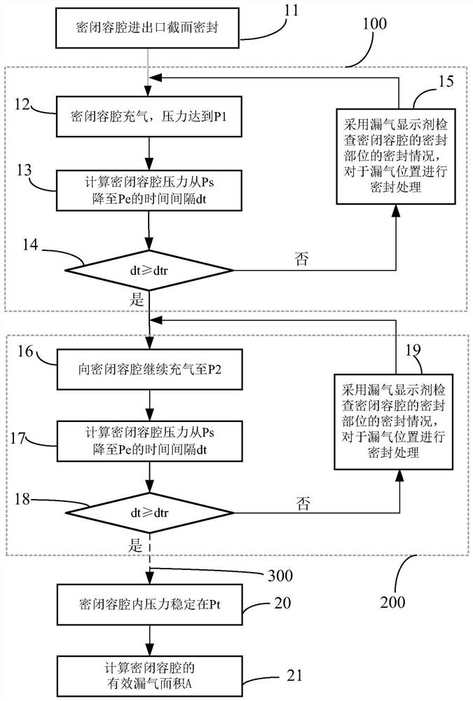
[0004] Aiming at the problem that the traditional sealing inspection cannot quantitatively evaluate the degree of sealing, the present invention provides a method for inspecting the airtightness of a closed cavity, which includes the following steps:

Method used

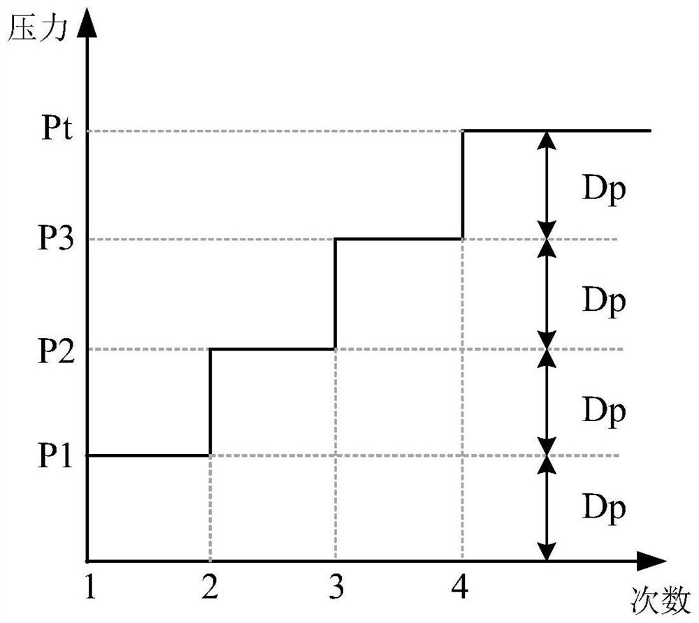
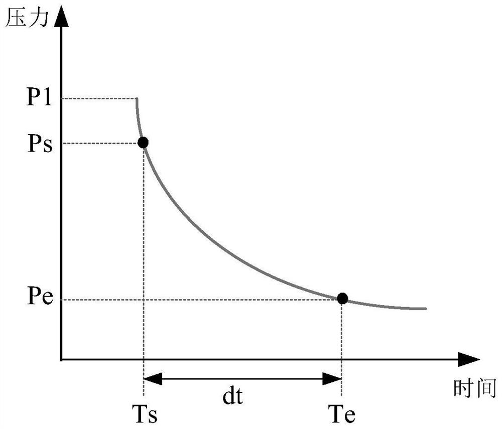

Image

  • Method for checking airtightness of closed cavity
  • Method for checking airtightness of closed cavity
  • Method for checking airtightness of closed cavity

Examples


Embodiment Construction

[0024] The present invention will be further described below in conjunction with specific embodiment and accompanying drawing, set forth more details in the following description so as to fully understand the present invention, but the present invention can obviously be implemented in many other ways different from this description, Those skilled in the art can make similar promotions and deductions based on actual application situations without violating the connotation of the present invention, so the content of this specific embodiment should not limit the protection scope of the present invention.

[0025] It should be noted that these and other subsequent drawings are only examples, and should not be construed as limiting the protection scope of the actual claims of the present invention.

[0026] In the following embodiments, the airtight chamber is described by taking the air inlet, the air outlet, and the closed space formed by the sealed gas turbine engine or component...


PUM


Abstract

A method for checking the airtightness of a closed cavity comprises the following steps of: inflating the closed cavity by adopting inflating equipment until the pressure of the closed cavity reaches a preset value Pt; keeping the pressure Pt of the closed cavity unchanged in a continuous inflation mode; measuring the inflation mass flow Wt of continuous inflation, wherein the environment pressure is measured to be P0, and the environment temperature is measured to be T0; calculating a pi (lambda) value of leaked gas, performing looking up according to an aerodynamic function table to obtain a corresponding lambda value and a flow function q (lambda) value, calculating an effective gas leakage area A of the closed cavity, and conveniently and quantitatively evaluating the gas tightness degree of the closed cavity by calculating the effective gas leakage area A, and showing that the gas tightness is worse when the value A is larger.

Description

technical field [0001] The invention relates to the field of casing testing of gas turbine engines and components thereof, in particular to air tightness inspection. Background technique [0002] In order to meet the needs of processing and assembly, gas turbine engines are designed with casings, such as intake casings, front power casings, combustion chamber casings, etc., and the casings are connected by flanges. For the needs of engine work, control, monitoring, etc., there are a large number of mounting seats for bleed air, fuel oil, lubricating oil, cables, machinery, etc. on the casing wall. When the engine is working, if the sealing between the casings or various mounting seats on the casing is poor, it will cause the high-temperature gas inside the gas turbine to leak. On the one hand, the leaked high-temperature gas will enter the engine compartment, causing the temperature of the engine compartment to be too high, threatening the safe operation of fuel, lubricatin...

Claims


Application Information

Patent Timeline
Patent Type & Authority Applications(China)
IPC IPC(8): G01M3/26
CPCG01M3/26
Inventor 骆广琦赵运生斯夏依薛冰晶
Owner AECC COMML AIRCRAFT ENGINE CO LTD
Learn More