Eureka AIR delivers breakthrough ideas for toughest innovation challenges, trusted by R&D personnel around the world.

Foundation pit support structure and construction method thereof

A technology for foundation pit enclosure and enclosure structure, which is applied in foundation structure engineering, excavation, sheet pile wall, etc., can solve the problems of reducing the speed of overall civil construction, long construction period, etc., and achieves easy implementation, convenient construction, enhanced holistic effect

Pending Publication Date: 2022-02-25
中城建(福建)建筑设计研究院有限公司
View PDF6 Cites 0 Cited by
  • Summary
  • Abstract
  • Description
  • Claims
  • Application Information

AI Technical Summary

Problems solved by technology

[0004] Not only must the stability of the foundation pit and the safety and convenience of the operation in the pit be guaranteed, but also the displacement of the soil at the bottom of the pit and outside the pit must be controlled within a certain range to ensure the normal use of adjacent buildings and municipal facilities; Most of the buildings use reinforced concrete structures for support and reinforcement, but the construction period of this technology is longer, which reduces the speed of the overall civil construction

Method used


Image

  • Foundation pit support structure and construction method thereof
  • Foundation pit support structure and construction method thereof
  • Foundation pit support structure and construction method thereof

Examples


Embodiment 1

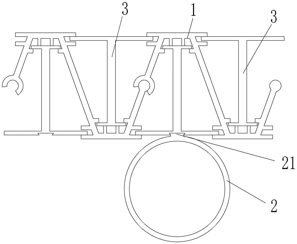
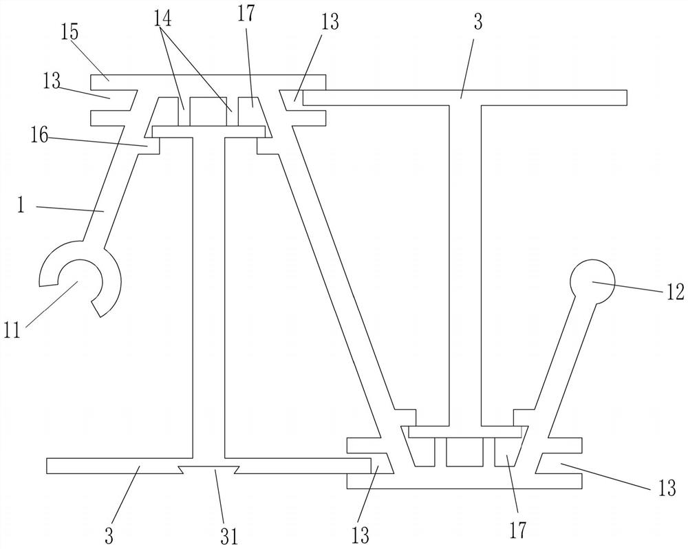
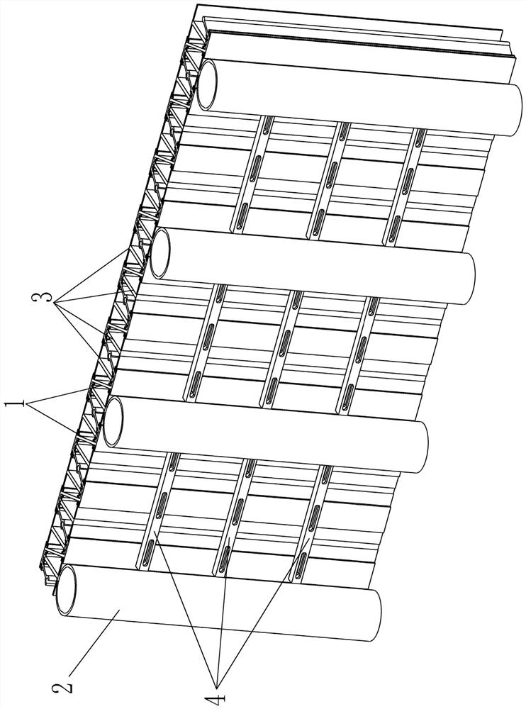
[0051] The two steel sheet piles 1 are occluded and connected to each other through the occlusal structure provided to form a continuous enclosure structure; the I-shaped steel pile 3 is clamped at the corner 17 on both sides of the steel sheet pile 1, and the I-shaped steel pile 3 and A triangular structure is formed between two connected steel sheet piles 1; several steel pipe piles 2 are connected to the non-blocking side of the enclosure structure, and the steel pipe piles 2 are connected to the I-shaped steel piles 3 at intervals; The steel sheet piles 1 between the two steel pipe piles 2 are connected by multiple sets of beams 4 , and the two ends of the beams 4 are respectively welded to the two steel pipe piles 2 .

[0052] Among them, this embodiment one can be applied to the enclosure structure formed by the enclosure in the deeper foundation pit; through the connection of the steel sheet pile 1 and the I-shaped steel pile 3, it forms a stable triangular structure, wh...

Embodiment 2

[0054] The two steel sheet piles 1 are occluded and connected to each other through the occlusal structure provided to form a continuous enclosure structure; the I-shaped steel pile 3 is clamped at the corner 17 on the same side of the steel sheet pile 1, and the I-shaped steel pile 3 and A triangular structure is formed between two connected steel sheet piles 1; wherein, the corner 17 on the other side of the steel sheet pile 1 is not clamped with an I-shaped steel pile 3; block side, and the steel pipe piles 2 are connected to the I-shaped steel piles 3 at intervals; the steel sheet piles 1 between two adjacent steel pipe piles 2 are connected by multiple sets of beams 4, and Welded on two steel pipe piles 2 respectively.

[0055] Among them, this embodiment one can be applied to the enclosure structure formed by the enclosure in the deeper foundation pit; through the connection of the steel sheet pile 1 and the I-shaped steel pile 3, it forms a stable triangular structure, ...

Embodiment 3

[0057] The two steel sheet piles 1 are interlocked and connected to each other through the interlocking structure provided therein, forming a continuous enclosure structure.

[0058] Wherein, the third embodiment can be applied to an enclosure structure formed by enclosure in a relatively shallow foundation pit; the structure is simple, the construction is convenient, easy to implement, and high in safety.

[0059] Additionally, if Figure 1-4 As shown, the present invention provides a kind of construction method of above-mentioned foundation pit enclosure structure, comprises the following steps:

[0060] S1, implanting the steel sheet pile 1; in the soft soil layer, insert the steel sheet pile 1 into the soft soil layer directly along the boundary line of the foundation pit enclosure; the clamping strip 12 provided by the steel sheet pile 1 is inserted into the adjacent steel plate The pile 1 is provided in the first clamping groove 11.

[0061] S2, inserting the I-shaped ...


PUM


Abstract

The invention discloses a foundation pit support structure. The support structure is composed of a plurality of steel sheet piles, steel pipe piles, cross beams and I-shaped steel piles. The two steel sheet piles are connected in a meshed mode through the meshing structures of the steel sheet piles, a continuous enclosure structure is formed, and the double functions of water stopping and soil retaining are achieved. The cross section of each steel sheet pile in the length direction is in a Z shape, each I-shaped steel pile is connected to the inner side of one corner of the corresponding steel sheet pile, and each I-shaped steel pile and the corresponding two connected steel sheet piles form a triangular structure. The plurality of steel pipe piles are connected to the I-shaped steel piles at intervals; the steel sheet piles located between every two adjacent steel pipe piles are connected through a plurality of sets of cross beams. The structure and the method disclosed by the invention are flexible and diversified; in practical engineering, flexible selection and arrangement can be achieved according to site conditions, the structure is simple, construction is convenient, implementation is easy, safety is high, and a new thought is provided for the supporting form of canceling an inner support for a deep foundation pit or an ultra-deep foundation pit.

Description

technical field [0001] The invention relates to the technical field of civil engineering, in particular to a foundation pit enclosure structure and a construction method thereof. Background technique [0002] The foundation pit refers to the space below the ground excavated for the construction of the foundation and basement of buildings (including structures). conduct. [0003] Foundation pit enclosure is a method for developing and utilizing underground space and constructing various underground buildings such as multi-storey basements, underground railways, and underground commercial streets: there are gravity-type mixing pile retaining walls, underground diaphragm walls, and pile-row retaining walls. [0004] Not only must the stability of the foundation pit and the safety and convenience of the operation in the pit be guaranteed, but also the displacement of the soil at the bottom of the pit and outside the pit must be controlled within a certain range to ensure the no...

Claims


Application Information

Patent Timeline
Patent Type & Authority Applications(China)
IPC IPC(8): E02D17/04E02D5/04E02D5/08E02D5/28E02D19/18
CPCE02D17/04E02D5/04E02D5/08E02D5/28E02D19/18E02D5/285
Inventor 章亚光冯望
Owner 中城建(福建)建筑设计研究院有限公司
Why Eureka
Eureka Blog
Learn More