Pipeline protection effect detection device and detection method

A protection effect and detection device technology, applied in the field of pipeline protection effect detection devices, can solve the problems of inability to measure pipelines, inability to evaluate the effectiveness of cathodic protection in crossing sections, lack of equipment and methods for evaluating the effectiveness of cathodic protection of directional drilling, and the like. Rich data detection effect, guaranteed service life, low construction cost effect

Pending Publication Date: 2022-02-25
PETROCHINA CO LTD
View PDF3 Cites 1 Cited by
  • Summary
  • Abstract
  • Description
  • Claims
  • Application Information

AI Technical Summary

Problems solved by technology

[0003] At present, the evaluation methods for the protection effect of directional drilling crossing section mainly include current-potential method, PCM current decay method and numerical simulation method. The standard NACETM0102 uses the current-potential method to evaluate the quality of the anti-corrosion layer in the crossing section, but this method is only applicable to construction. Pipelines that have not been connected to other pipe sections after completion cannot be measured for pipes that have been connected; the PCM current decay method detection instrument can only test the protection potential at both ends of the crossing section, but cannot evaluate the cathodic protection effectiveness of the crossing section; the numerical simulation method can Evaluate the change law between the cathodic protection and the defect rate of the pipeline crossing section, but the boundary conditions of the numerical calculation are artificially stipulated, which is different from the actual boundary conditions of the crossing section. It can be found that domestic and foreign cathodic protection evaluation It is still basically in the detection and evaluation stage of the anti-corrosion layer. The cathodic protection potential distribution of the pipeline crossing section has only been explored in numerical simulation, and the accuracy of the numerical simulation calculation results needs to be further verified. Equipment and methods for evaluation of protection effectiveness

Method used


Image

  • Pipeline protection effect detection device and detection method
  • Pipeline protection effect detection device and detection method
  • Pipeline protection effect detection device and detection method

Examples


Embodiment Construction

[0031] In order to understand the above-mentioned purpose, features and advantages of the present invention more clearly, the present invention will be further described in detail below in conjunction with the accompanying drawings and specific embodiments. It should be noted that, in the case of no conflict, the embodiments of the present application and the features in the embodiments can be combined with each other.

[0032] In the following description, many specific details are set forth in order to fully understand the present invention. However, the present invention can also be implemented in other ways different from those described here. Therefore, the protection scope of the present invention is not limited by the specific details disclosed below. EXAMPLE LIMITATIONS.

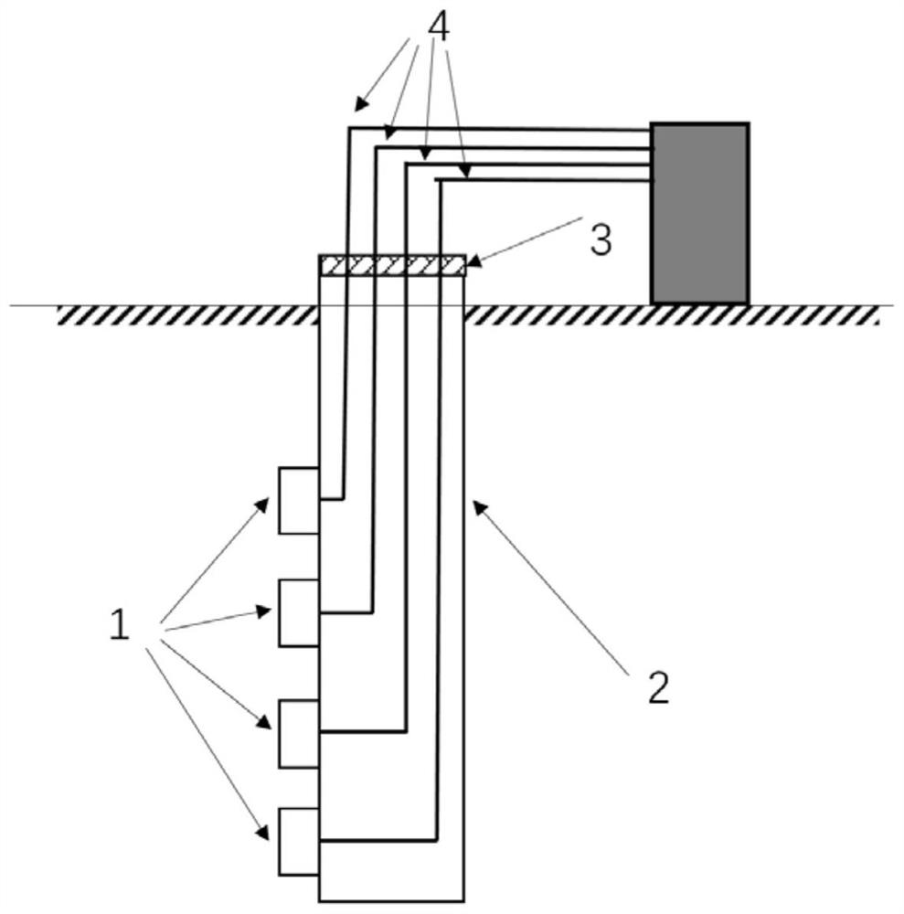
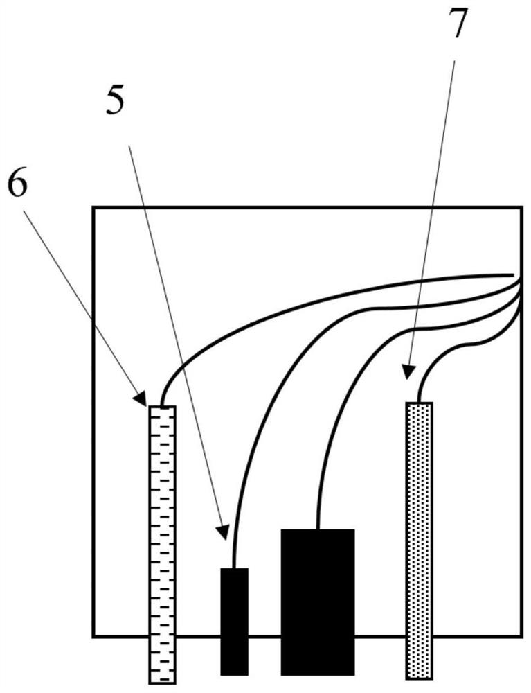
[0033] Such as Figure 1 to Figure 2 As shown, according to the first aspect of the embodiment of the present application, a pipeline protection effect detection device is proposed, including: testi...


PUM

PropertyMeasurementUnit
diameteraaaaaaaaaa
diameteraaaaaaaaaa

Abstract

The embodiment of the invention provides a pipeline protection effect detection device and method, and relates to the technical field of pipeline protection. The detection device comprises testing equipment; a connecting assembly, of which one end is connected to the testing equipment and the other end is used for extending to the position below the earth surface; a supporting piece which is used for fixing and supporting part of the connecting assembly; a cover plate which is arranged at the top end of the supporting piece in a sealing mode. and a plurality of probe assemblies which are respectively arranged at different height positions of the supporting piece and are connected to the connecting assembly, each probe assembly comprising a plurality of test connecting lines. According to the pipeline protection effect detection device, more abundant data support can be obtained through reference electrodes made of two different materials, and the requirement of a user for pipeline protection effectiveness evaluation is met.

Description

technical field [0001] The invention relates to the technical field of pipeline protection, in particular to a pipeline protection effect detection device and detection method. Background technique [0002] Directional drilling is a non-excavation technology that does not damage the stratum structure, occupies less land, is not affected by seasons, and has a short construction period. However, pipelines constructed by directional drilling technology have long been in deep underground or underwater service. Due to difficulties in repair and replacement, routine measurement and evaluation of the effectiveness of cathodic protection cannot be carried out on the directional drilling crossing section in service. If directional drilling cannot be mastered With the anti-corrosion coating and cathodic protection level outside the crossing section, the long-term corrosion is very likely to cause corrosion leakage and cause production safety accidents. Therefore, timely evaluation of...

Claims


Application Information

Patent Timeline
Patent Type & Authority Applications(China)
IPC IPC(8): C23F13/22
CPCC23F13/22C23F2213/32
Inventor 马汝彦郭大成唐德志张维智卢洪源陈宏健杜艳霞马海峰王茁姜锦涛杨海燕庄大伟胡静
Owner PETROCHINA CO LTD
Why Eureka
Try Eureka