Double-end automatic feeding lens placement machine

An automatic feeding and placement machine technology, applied in the direction of conveyor objects, installation, material gluing, etc., can solve the problems of labor consumption, waste, motor speed limit, etc., to reduce the price of the machine, reduce the price, and ensure the accuracy of feeding Effect

Pending Publication Date: 2022-02-25
广东索能光电技术有限公司
View PDF0 Cites 0 Cited by
  • Summary
  • Abstract
  • Description
  • Claims
  • Application Information

AI Technical Summary

Problems solved by technology

But, there are following problems in existing lens mounting machine: 1, machine cost is high
Existing lens placement machines generally require high mechanical precision and electrical control costs, and most small and medium-sized LED lamp manufacturers cannot purchase them.
2. Not Compatible
Since the LED lenses and light panels used by various manufacturers have many differences in details, and the lens mounting machine requires high precision, most of the lens machines on the market are not compatible. Generally, one machine can only mount one kind of lens
3. Cannot be placed circularly
Each placement needs to start from a fixed point, and a lot of time is wasted on operations such as machine return to zero
4. The lens with corners is easy to jam and fly
For lenses with corners, it is easy for the corners to press each other in the direct vibration and reclaiming positions, resulting in material jams or materials pressing each other, the suction nozzle cannot suck the lens, and even the material is blown away by the feeding air pipe after half suction. Happening
5. Dispensing and handling are labor-intensive
Many lenses need to be glued on the PCB first, and then the lens is mounted, and the handling after dispensing and dispensing requires a lot of labor.
6. The existing single-nozzle placement machine is limited by the motor running speed and has limited efficiency; the multi-nozzle placement and placement machine cannot be widely promoted due to the difficulty of machine debugging and cost constraints

Method used


Image

  • Double-end automatic feeding lens placement machine
  • Double-end automatic feeding lens placement machine
  • Double-end automatic feeding lens placement machine

Examples


Embodiment Construction

[0028] The following will clearly and completely describe the technical solutions in the embodiments of the present invention with reference to the accompanying drawings in the embodiments of the present invention. Obviously, the described embodiments are only some of the embodiments of the present invention, not all of them. Based on the embodiments of the present invention, all other embodiments obtained by persons of ordinary skill in the art without making creative efforts belong to the protection scope of the present invention.

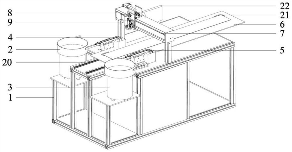
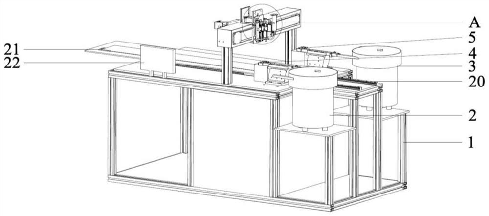
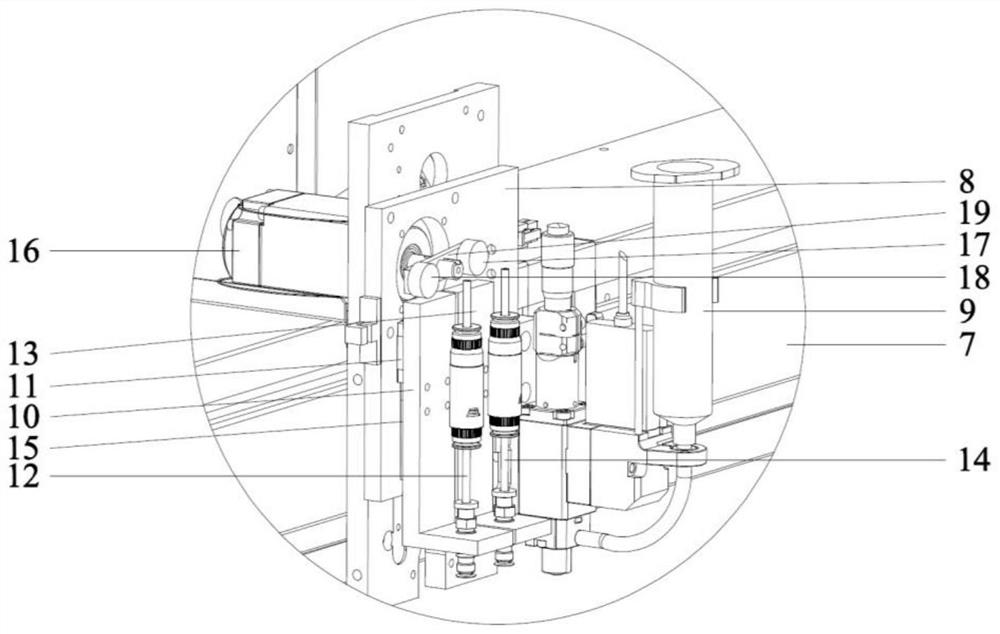
[0029] Such as Figure 1 to Figure 3A kind of double-head automatic feeding lens placement machine of the present invention as shown, comprises frame 1, and the front part and rear part of frame 1 left side are installed with first vibrating plate 2 and second vibrating plate 3 respectively, and the first vibrating plate The right side of 2 is provided with the first feeding positioning module 4 connected with the first vibrating plate 2, the rig...


PUM


Abstract

The invention discloses a double-end automatic feeding lens placement machine. The double-end automatic feeding lens placement machine comprises a rack; a first vibration disc and a second vibration disc are installed on the front portion and the rear portion of the left side of the rack correspondingly. A first feeding positioning module connected with the first vibration disc is arranged on the right side of the first vibration disc, and a second feeding positioning module connected with the second vibration disc is arranged on the right side of the second vibration disc. The top of the rack is slidably connected with a lamp panel containing platform arranged in the left-right direction. The rack is provided with a first driving device for driving the lamp panel placing platform to move left and right; a supporting frame arranged in the front-back direction is installed at the top of the rack. The supporting frame is slidably connected with a mounting base moving in the front-back direction. And a second driving device for driving the mounting base to move back and forth is mounted on the inner side of the supporting frame. The invention is simple in structure and low in manufacturing cost, adhesive dispensing and lens mounting are automatically achieved, the labor cost is saved, and the production efficiency is improved.

Description

technical field [0001] The invention relates to the technical field of LED lamp processing, in particular to a double-head automatic feeding lens mounting machine. Background technique [0002] In the LED lighting industry, in order to gather light sources, lenses are generally mounted on LED chips for light gathering. The traditional way of mounting the lens is to manually place the lens into the light board through the hook or glue. In recent years, there are machines that use the principle of SMT placement machine to replace the manual lens mounting. In the way of identification, the lens is automatically placed by the robot. However, the existing lens mounter has the following problems: 1. The cost of the machine is high. Existing lens mounting machines generally require high mechanical precision and electrical control costs, and most small and medium-sized LED lamp manufacturers cannot purchase them. 2. Not compatible. Since the LED lenses and light panels used by v...

Claims


Application Information

Patent Timeline
Patent Type & Authority Applications(China)
IPC IPC(8): B05C5/02B65G47/14B65G47/91F16B11/00G02B7/02
CPCB05C5/0208B65G47/14B65G47/91F16B11/006G02B7/02G02B7/025
Inventor 刘嫣然
Owner 广东索能光电技术有限公司
Why Eureka
Try Eureka