Electric heating device and method for producing same

A technology of electric heating devices and heating chambers, applied in the direction of electric heating devices, immersion heating devices, ohmic resistance heating, etc., can solve safety problems and other problems, and achieve the effects of compact structure, good dimensional stability, and firm fluid-tight connection

Pending Publication Date: 2022-02-22
EBERSPACHER CATEM
View PDF2 Cites 0 Cited by
  • Summary
  • Abstract
  • Description
  • Claims
  • Application Information

AI Technical Summary

Problems solved by technology

In particular, when the electric heating device is used in an electric vehicle, where the on-board power supply is also used to operate the electric heating device, this drawback causes considerable safety problems

Method used


Image

  • Electric heating device and method for producing same
  • Electric heating device and method for producing same
  • Electric heating device and method for producing same

Examples


Embodiment Construction

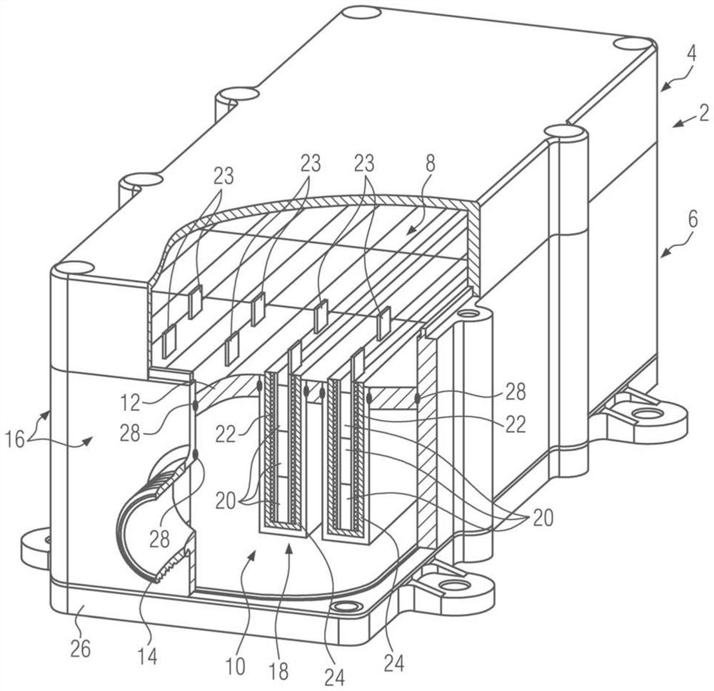
[0029] In the figures, reference numeral 2 designates a housing with a housing upper part 4 and a housing lower part 6 . The housing upper part 4 surrounds the connection chamber 8 . The housing lower part 6 surrounds the heating chamber 10 . A partition wall 12 is located between the heating chamber 10 and the connection chamber 8 . The partition wall 12 is fluid-tight so that the liquid fluid to be heated contained in the heating chamber 10 cannot reach the connection chamber 8 . At the level of the heating chamber 10 , the housing 2 stands above via a connection port 14 for connecting fluid-conducting lines within the motor vehicle. These connection ports 14 protrude from an opposite housing wall 16 which in the present example surrounds the heating chamber 6 in the circumferential direction. In this figure, only one of these connection ports 14 is visible, ie partially cut away.


PUM


Abstract

The invention relates to an electric heating device having a housing, comprising a housing (2) having a partition wall (12) which separates a connection chamber (8) from a heating chamber (10) for dissipating heat, and from which partition wall (12) at least one heating element housing (18) protrudes in the direction of the heating chamber (10), wherein at least one PTC element (20) and a bar conductor (22) are supported in an electrically insulating manner in the heating assembly housing (18), the bar conductor (22) is connected to the PTC element (20) in an electrically conductive manner in order to excite the PTC element (20) with different polarities, and the bar conductor (22) is electrically connected in the connection chamber (8). A compact electric heating device is achieved in which a housing wall (16), which protrudes from the partition wall (12) and delimits the connection chamber (8) and / or the heating chamber (10) and / or the heating assembly housing (18), is connected to the partition wall (12) by means of material bonding, in particular by means of induction brazing.

Description

technical field [0001] The invention relates to an electric heating device having a housing comprising a partition wall separating a connection chamber from a heating chamber for dissipating heat. At least one PTC heating element protrudes from the partition wall in the direction of the heating chamber. The PTC heating elements are exposed in the heating chamber in the form of heating ribs. The PTC heating assembly has at least one PTC element and strip conductors electrically connected to the PCT element, the conductors being assigned different polarities for exciting the PTC element. These strip conductors are electrically connected to the supply current in the connection chamber. Background technique [0002] Such a heating device is known, for example, from EP 2 337 425 A1. In such an electric heating device, the partition wall is configured in one piece with a heating element housing which protrudes as heating ribs into the heating chamber. In the aforementioned pri...

Claims


Application Information

Patent Timeline
Patent Type & Authority Applications(China)
IPC IPC(8): H05B3/82H05B3/50H05B3/32H05B3/24H05B3/14H05B3/10H05B3/06H05B3/04H05B3/03H05B3/02H05B1/02F24H9/20F24H3/04F24H1/12F24H1/10F24H1/00B60H1/22
CPCH05B3/50F24H1/102H05B3/14F24H1/121H05B3/02H05B3/82B60H1/2215B60H1/2221H05B3/146H05B3/141H05B3/10H05B3/32H05B3/06F24H9/2014H05B3/03H05B3/04F24H1/009H05B1/0236H05B1/0244F24H9/2071F24H3/0429H05B3/24H05B2203/02H05B2203/023B60H2001/2278F24H2250/04H05B2203/021H05B2203/017B23K1/002H05B2203/016
Inventor 安德雷斯·克林格比尔迪特马尔·温斯多夫卡尔斯滕·鲍尔茨阿尔弗雷德·布鲁姆
Owner EBERSPACHER CATEM
Why Eureka
Try Eureka