Eureka AIR delivers breakthrough ideas for toughest innovation challenges, trusted by R&D personnel around the world.

Self-following method and automatic following device

A technology of automatic following and horizontal direction, applied in the direction of finding the target control, etc., can solve the problem of unusable, etc., and achieve the effect of low cost and good environmental adaptability

Pending Publication Date: 2022-02-18
重庆庄周科技有限责任公司
View PDF0 Cites 0 Cited by
  • Summary
  • Abstract
  • Description
  • Claims
  • Application Information

AI Technical Summary

Problems solved by technology

[0002] In recent years, with the development of computer technology and wireless communication technology, intelligent devices have appeared more and more frequently in people's lives, especially unmanned aerial vehicles, which have been widely used in military and civilian fields. As one of the core technologies of UAVs, technology has been extensively studied by academia and industry. There are two main technical solutions for the realization of automatic following technology: (1) Automatic following based on GPS positioning. This technical solution needs to be GPS modules are installed inside the UAV and mobile devices (such as remote controls), and the relative position of the UAV and the subject is determined through the precise positioning of GPS. The flight control system controls the UAV according to the relative position of the two to realize automatic Following function, the solution must ensure the accuracy of the GPS signal, which cannot be used in mountainous areas or indoors where the signal is weak; (2) Vision-based following, this technology requires that the following target is highly recognizable relative to the surrounding environment, and at the same time following the target needs to be constantly Keep within the capture range of the camera, "can't find the target" will cause the visual follow to be forced to stop temporarily

Method used


Image

  • Self-following method and automatic following device
  • Self-following method and automatic following device

Examples


Embodiment Construction

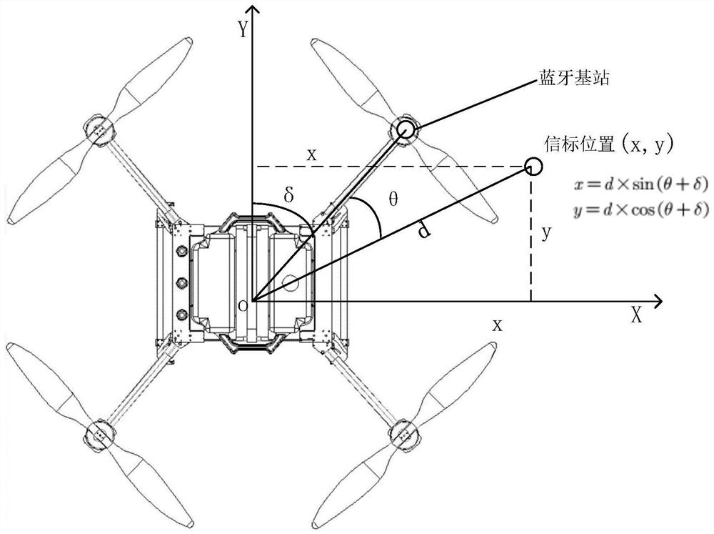
[0020] In order to better understand the solution of the present invention, the present invention will be further described in detail in conjunction with the invention of an unmanned aerial vehicle (that is, an automatic follower device) that adopts the method of the present invention.

[0021] A drone that includes a Bluetooth base station for connection to a mobile Bluetooth module, a barometer, and an accelerometer. During specific implementation, the mobile bluetooth module can be an unmanned aerial vehicle remote control integrated with a bluetooth module, or a smart device such as a bluetooth headset, a bluetooth bracelet, or a mobile phone with a bluetooth module. Since bluetooth earphones, mobile phones, and bluetooth bracelets are all popular commodities, the per capita possession rate is relatively high. Therefore, in this embodiment, the bluetooth base station is used as the signal receiving base station configured on the automatic follower device, and the bluetooth ...


PUM


Abstract

The invention discloses a self-following method and an automatic following device. The automatic following method comprises the following steps of S1, establishing connection between a signal receiving base station on the automatic following device and a signal sending module to be followed, S2, acquiring a received signal intensity value sent by the signal sending module in real time through a signal receiving base station, S3, controlling the automatic following device to drive the signal receiving base station to move along the circular track in the horizontal direction, acquiring all signal intensity values under the circular track, finding out the maximum value of the signal intensity values and the position of the signal receiving base station on the circular track when the maximum value is found out, and using the orientation of the position as the following direction of the automatic following device, and S4, repeating the step S3, and controlling the automatic following device to follow the signal sending module. The automatic following method and the unmanned aerial vehicle can meet the low-speed following requirement, and have the advantages of being low in implementation cost, good in environmental adaptability and the like.

Description

technical field [0001] The invention relates to the technical field of automatic follow-up, in particular to a self-following method and an automatic follow-up device. Background technique [0002] In recent years, with the development of computer technology and wireless communication technology, intelligent devices have appeared more and more frequently in people's lives, especially unmanned aerial vehicles, which have been widely used in military and civilian fields. As one of the core technologies of UAVs, technology has been extensively studied by academia and industry. There are two main technical solutions for the realization of automatic following technology: (1) Automatic following based on GPS positioning. This technical solution needs to be GPS modules are installed inside the UAV and mobile devices (such as remote controls), and the relative position of the UAV and the subject is determined through the precise positioning of GPS. The flight control system controls...

Claims


Application Information

Patent Timeline
IPC IPC(8): G05D1/12
CPCG05D1/12
Inventor 刘刚马于博刘永刚叶明
Owner 重庆庄周科技有限责任公司
Why Eureka
Eureka Blog
Learn More