Electric valve

An electric valve, valve core technology, applied in valve details, valve device, valve shell structure and other directions, can solve problems such as fluid noise, and achieve the effect of reducing fluid noise

Pending Publication Date: 2022-02-18
ZHEJIANG SANHUA AUTOMOTIVE COMPONENTS
View PDF0 Cites 0 Cited by
  • Summary
  • Abstract
  • Description
  • Claims
  • Application Information

AI Technical Summary

Problems solved by technology

[0002] In the system pipeline, the electric valve generally uses the spool to switch the fluid on and off. When the spool moves to make the fluid throttle at a small opening, at this time, under the influence of the pressure difference and flow rate, the fluid is easy to flow in the electric valve. The outlet channel of the valve forms a vortex area, which may generate fluid noise. How to reduce the fluid noise generated by the electric valve when it is working is a technical problem to be solved

Method used


Image

  • Electric valve
  • Electric valve
  • Electric valve

Examples


Embodiment Construction

[0015] Below in conjunction with accompanying drawing and specific embodiment the application is further described:

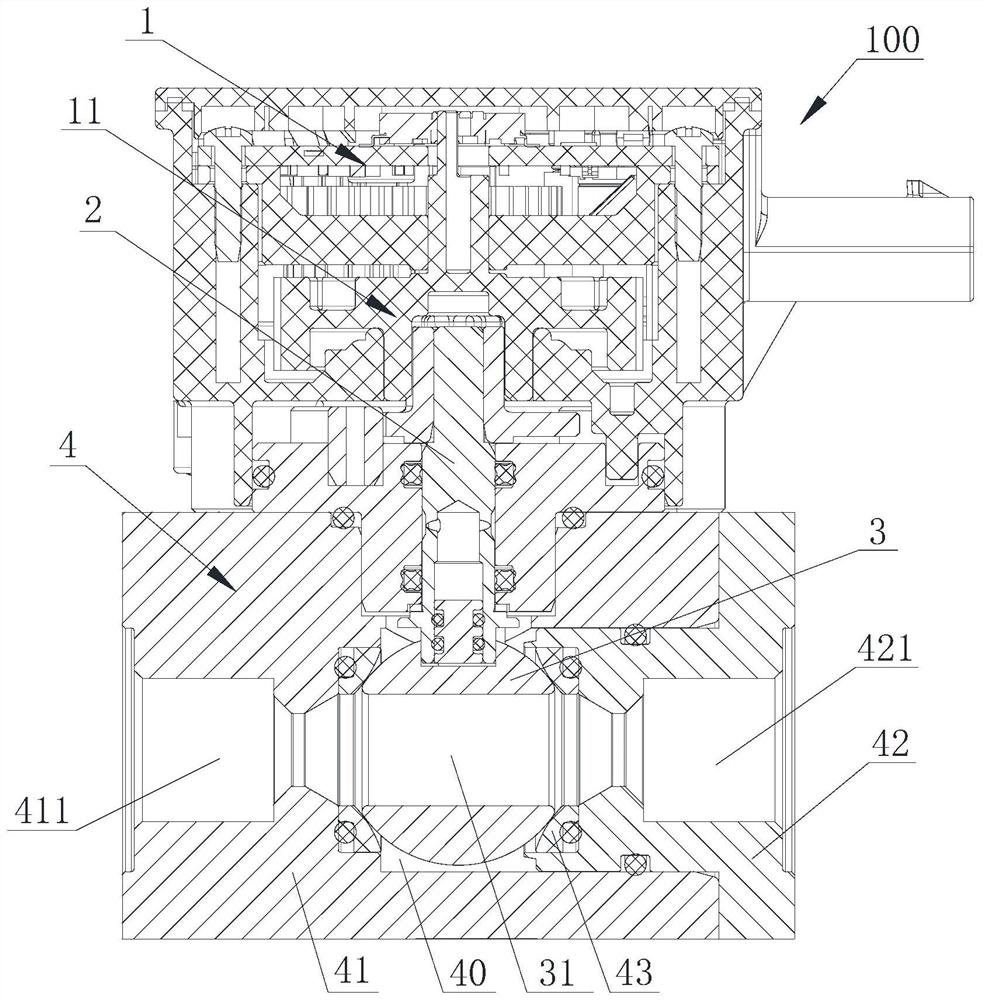
[0016] see figure 1 , the electric valve can be applied to the vehicle thermal management system, the vehicle thermal management system includes the new energy vehicle thermal management system, the electric valve 100 includes the control part 1, the valve stem 2, the valve core 3 and the valve body assembly 4, the valve core 3 is located in the valve body The valve body cavity 40 formed by the assembly 4, one end of the valve stem 2 is in transmission connection with the control part 1, and the other end of the valve stem 2 is in transmission connection with the valve core 3, the control part 1 outputs rotational torque to the valve stem 2, and the valve stem 2 drives the valve core 3 sports. In this embodiment, the valve core 2 is spherical, and the control part 1 also includes a transmission part 11, which can be a gear reduction mechanism. At least part of...


PUM


Abstract

The invention relates to an electric valve comprising a valve element, a valve body assembly and a first flow guide part, the valve body assembly is provided with a first channel and a second channel, the valve element is provided with a hole channel, the first flow guide part comprises a first inclined section and a straight section, the first inclined section is closer to the valve element than the straight section, and the first flow guide part forms a first flow guide cavity which is communicated with the first channel; the first flow guide cavity is closer to the valve element than the first channel, and the hole channel can communicate with the first channel and the second channel through the first flow guide cavity, so that when the valve element moves to enable fluid to be throttled at a small opening degree and the fluid flows in from the second channel, the fluid flows from the second channel to the first flow guide cavity after passing through the hole channel; the fluid flows out of the first channel after being guided by the first guide cavity, so that the possibility that the fluid forms vortex in the first channel is reduced, and the fluid noise generated when the electrically operated valve works is reduced.

Description

technical field [0001] The present application relates to an electric valve. Background technique [0002] In the system pipeline, the electric valve generally uses the spool to switch the fluid on and off. When the spool moves to make the fluid throttling at a small opening, at this time, under the influence of the pressure difference and flow velocity, the fluid is easy to flow in the electric valve. The outlet channel of the valve forms a vortex area, which may generate fluid noise. How to reduce the fluid noise generated by the electric valve when it is working is a technical problem to be solved. Contents of the invention [0003] The purpose of the present application is to provide an electric valve, which is beneficial to reduce the fluid noise generated when the electric valve is in operation. [0004] In order to achieve the above object, the application adopts the following technical solutions: [0005] An electric valve, comprising a valve core and a valve bod...

Claims


Application Information

Patent Timeline
IPC IPC(8): F16K5/06F16K5/08F16K27/06
CPCF16K5/06F16K5/08F16K27/067
Inventor 不公告发明人
Owner ZHEJIANG SANHUA AUTOMOTIVE COMPONENTS
Why Eureka
Try Eureka