Bridge steel strand integral strand penetrating device
A steel strand and integral technology, which is applied in the field of the overall stranding device of bridge steel strands, can solve the problem of uneven stranding tension, and achieve the effects of improving stranding efficiency, reducing cutting waste, and controlling stranding length.
- Summary
- Abstract
- Description
- Claims
- Application Information
AI Technical Summary
Problems solved by technology
Method used
Image
Examples
Embodiment 1
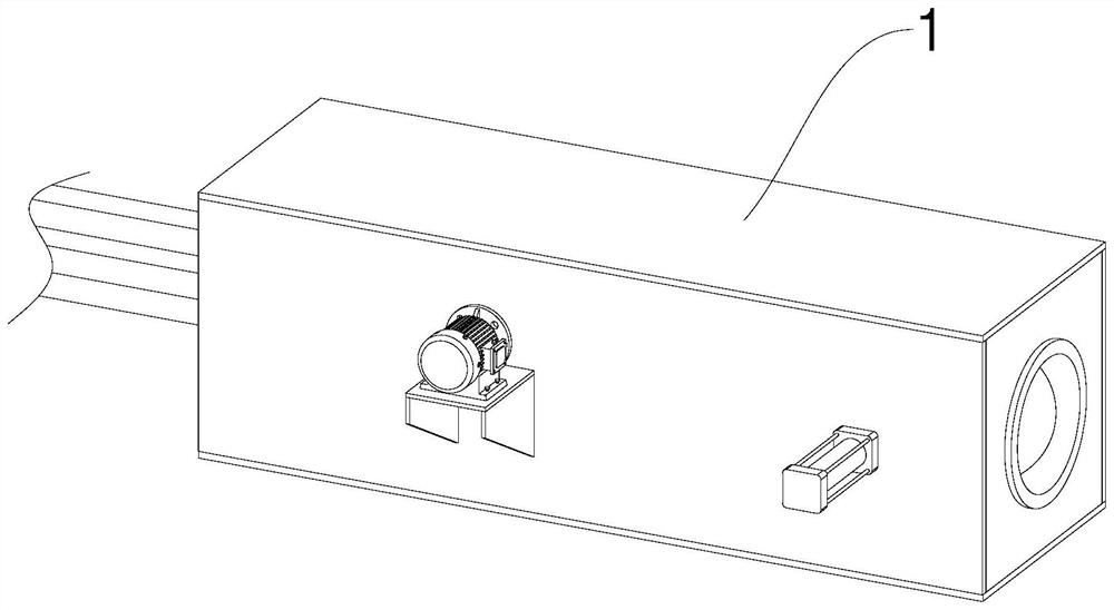
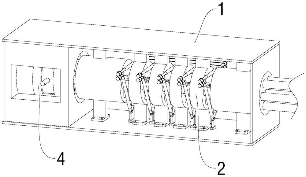
[0030] see Figure 1-2 , an overall beam threading device for bridge steel strands, including a rectangular sealed box 1, and also includes a beam threading conveying mechanism 2, the beam threading conveying mechanism 2 is installed inside the rectangular sealed box 1 for multiple cables simultaneously For beam transmission, the steel strand locks the beam threading head 3, and the beam threading conveying mechanism 2 is installed inside the rectangular sealed box 1 in parallel with the beam threading conveying mechanism 2 for docking, and multiple cables are connected for synchronous beam transmission. Holding and locking mechanism 4, the clamping and locking mechanism 4 is arranged on the outer side of the steel strand locking and threading head 3, and automatically performs the fixed connection between the steel strand locking and threading head 3 and multiple cables.
[0031] The present invention designs a device for synchronously threading a plurality of bridge steel st...
Embodiment 2
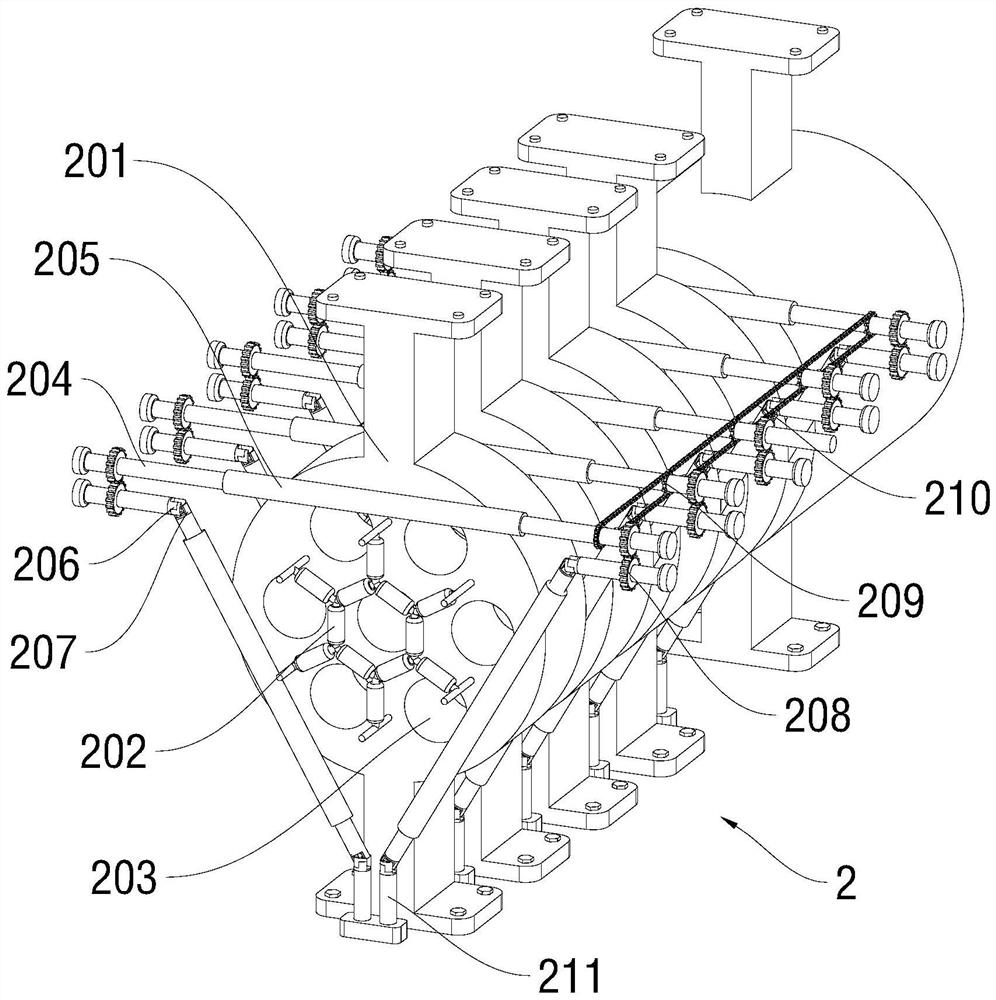
[0033] see Figure 2-3 , based on Embodiment 1, the difference is that the beam threading mechanism 2 includes a wire holder 201 and a wire holder 202; a plurality of the wire holders 201 are distributed along the same horizontal line and reserve gaps for each other, and the wire holders The upper and lower ends of 201 are connected to the inner wall of the rectangular sealed box 1 through brackets. The wire holder 201 is a cylindrical structure arranged horizontally and has a plurality of threading holes 203 uniformly. The wire holder 202 is installed between the two wire holders 201 The position between them is connected and fixed respectively.
[0034]The outside between the wire supports 202 is arranged in an inverted triangle structure, and three rotating shafts 204 are arranged. The middle parts of the rotating shafts 204 are sleeved with grinding rollers 205 that increase friction. The seat 201 is vertical, and the first universal joints 206 are sleeved on both ends of...
Embodiment 3
[0038] see Figure 5-9 , based on Embodiment 1-2, the difference is that the steel strand locking threading head 3 includes a fixed pipe 301 and a threading head 302, and the end of the threading head 302 is fixedly connected with an external threaded pipe 303, the externally threaded pipe 303 is inserted into the interior of the fixed pipe 301 and screwed to it, the inner wall of the fixed pipe 301 near the inner wall of the threaded pipe is fixed with a plurality of limit blocks 304 at equal intervals in a ring, the end of the fixed pipe 301 A fixed plate 305 in a T-shaped column structure is rotatably connected.
[0039] The other end of the fixed pipe 301 is provided with a first limiting hole 306 which is smaller than the hole diameter of the threading hole 203, and the inside of the fixed pipe 301 is provided with a turntable 307 close to the end of the first stop hole 306, and the turntable 307 is provided with a The same as the first limiting hole 306 and correspondin...
PUM
 Abstract
Description
Claims
Application Information
 - R&D
- Intellectual Property
- Life Sciences
- Materials
- Tech Scout
- Unparalleled Data Quality
- Higher Quality Content
- 60% Fewer Hallucinations
Browse by: Latest US Patents, China's latest patents, Technical Efficacy Thesaurus, Application Domain, Technology Topic, Popular Technical Reports.
© 2025 PatSnap. All rights reserved.Legal|Privacy policy|Modern Slavery Act Transparency Statement|Sitemap|About US| Contact US: help@patsnap.com


